Abstract
The decomposition of organic matter represents a fundamental pedogenetic process, since it impacts the carbon cycle and the release of nutrients to the soil. However, quantitative research aimed at micro-scale in situ analysis is scarce, despite its relevance in the decomposition process. Therefore, the objectives of this research were to generate discriminating functions of the degrees of organic matter decomposition, based on the brightness values associated with each morphological stage, and from this step, to generate thematic maps. Soil thin sections of forest and compost soils were selected, and petrographic microscope images with three light sources were taken: plane polarized light (PPL), crossed-polarized light (XPL), and crossed polarizers and a retardation plate (gypsum compensator) inserted (XPLλ). Subsequently, the RGB (red, green, blue) image was broken down into three bands, resulting in nine bands for each image. Two thousand sampling points were generated for each band, obtaining brightness values for each decomposed organic matter stage. The points were classified into four categories based on their degree of decomposition: no (A), light (B), moderate (C), and strong (D), in addition to porosity (P). Linear discriminant analysis was performed to obtain classification models for each level of decomposition. The results show that each degree of organic matter decomposition can be highlighted through specific light sources and a set of bands, with an overall accuracy of >94% and kappa coefficients of >0.75 for all classes. In addition, the resulting functions were validated in training images and high-resolution mosaics to create final thematic maps. The use of linear models automated the production and quality of thematic maps at the microscopic level, which can be useful in monitoring the organic matter decomposition process.
Introduction
The decomposition of organic matter represents a fundamental pedogenic and pedomorphological process (Fanning and Fanning, 1989), where mineralization, humification, stabilization and melanization have been widely studied (Zech et al., 1997). Nevertheless, little research has been done at fine scale despite its importance in particle stabilization (Brzychcy and Zagórski, 2010).
Soil micromorphology describes organic components at microscopic level using undisturbed soil samples (Bullock et al., 1985); nonetheless, their description is complex because their characteristics change swiftly during the decomposition process (Stoops, 2003). Colour, opacity, and birefringence are some criteria used to characterize the subtypes of organic components (Bullock et al., 1985; Stoops, 2003); these criteria however, may be subjective with quantification since the decomposition of organic matter is a diffused-nature feature rather than a discrete feature (Bullock et al., 1985).
Image analysis of soil thin sections to study different soil components (Protz et al., 1992; Terribile and Fitzpatrick, 1995; Taina and Heck, 2010; Brzychcy et al., 2012; Jangorzo et al., 2014; Gutiérrez-Castorena et al., 2018) has been an adaptation based on remote sensing techniques (Protz et al., 1987; Ringrose-Voase, 1991; Protz and VandenBygaart, 1998). These routines have made it possible to eliminate the subjective description of soil thin sections (Skvortsova and Sanzharova, 2007), allowing better understanding of soil morphological process and their impacts on processes at greater geographical scale, such as ecosystems resiliency and adaptation, among others. In spite of that, the study of organic components and their dynamics at microscale has been little addressed, due to the complexity of their features (Poch 2015), and as a result of the changes that occur within the humification process in a relatively short period of time (Stoops, 2003).
Gutiérrez-Castorena et al. (2018) proposed to use the brightness levels of organic components from composite (RGB) images. This method provided a gain of information; yet it requires an elaborate and complex image processing routine. Other authors (Ringrose-Voase, 1991; Marschallinger, 1997; Terribile et al., 1997) have therefore, proposed the use of multivariate techniques when complexity is associated with the identification of soil components. One of these multivariate techniques is Linear Discriminant Analysis (LDA), which allows selecting, reducing variables, and generating classification models (Mika et al., 1999; Brown and Wicker, 2000; Hallinan, 2012). In addition, through the application of LDA it is possible to choose the best light source, band or set of bands handling visible light compositions (RGB) that present the highest sharpness and contrast of the organic feature. The hypothesis was: “since each image consists of pixels associated with a numerical value, it is also possible to create models to produce thematic maps using brightness values, and to quantify the organic features produced during the different stages of organic matter decomposition at microscopic level.
Therefore, the objectives of this research were: to generate linear discriminant functions based on the brightness values of each level of organic matter decomposition and to produce thematic maps at the microscopic scale in individual images and high-resolution mosaics of the whole soil thin section.
Materials and Methods
The methodology used in this research consists of six steps, as illustrated in Figure 1.
FIGURE 1
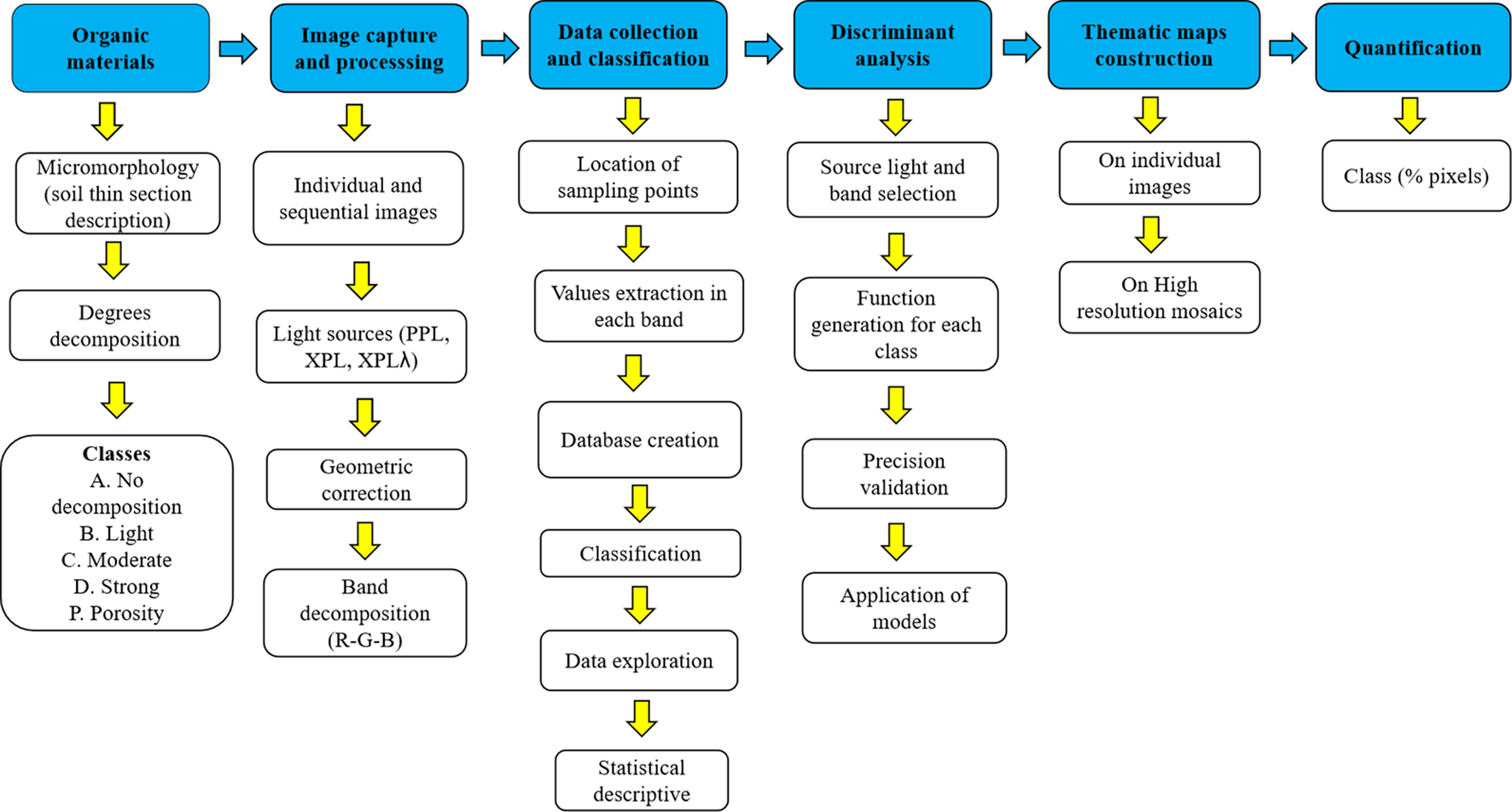
Flow diagram of the procedure developed in the investigation. PPL = Plain polarized light; XPL = Cross-polarized light; XPLλ = Cross-polarized light with gypsum compensator. R = Red, G = Green, B = Blue.
Organic Materials and Their Micro-Morphological Description
We selected twenty soil thin sections corresponding to various surface horizons (O and H) of two soil classes (Andosols and Histosols) across the Valley of Mexico, plus one obtained from composting and vermicomposting material, to quantify various features of organic materials we wished to study. The description of the organic components of the sections studied is reported in Table 1. The description of organic components with different degrees of decomposition was based on their colour, internal structure and opacity in PPL, and birefringence and isotropy in XPL, according to the terminology proposed by Bullock et al. (1985) and Stoops (2003). Consequently, four classes were established: A) Not decomposed (internal structure and birefringence); B) Light (internal structure and birefringence), C) Moderate (internal structure, opacity, and isotropy), and D) Strong (opacity and isotropy); in addition, a category corresponding to the porous system P (transparency in PPL and isotropy in XPL) was added, as reported in Table 2.
TABLE 1
| Soil/compost | Description |
|---|---|
| Andosol | Abundant Cupressus sp. leaves, reddish-brown on inner tissues and dark brown on epidermis; opaque in XPL; moderate preservation. Common leaf controns, moderate to strong decomposition. Few fine roots, light brown in PPL and birefringent in XPL, moderate preservation. Few microaggregates and few reddish brown hyphae. 65% porosity. Fine, common excrements of mite (Oribatid). 65% porosity. Monte Tláloc, Texcoco, Mexico. |
| Acrisol | Plan residues of Pinus sp.; moderate to a strong degree of preservation needles residues; abundant leaf comminuted; abundant coarse contours with a high degree of decomposition; coalescence and abundant fine excrements of mites; abundant actinomycetes. Oaxaca, Mexico. |
| Andosol | Roots and tissues residues (parenquimatic, and lignified tissues), moderate preservation; fine organic material (cell residues, spores, and hyphae), and amorphous fine material. Coarse, and well-preserved roots and fine common contours; few charcoal residues; few excrements. Texcoco, Mexico. |
| Organic amendments | Frequent, moderate to strong degree of preservation of organ and tissues of vegetables and fruits (oranges, nopales, lettuce leaves, etc.); common organ and tissues fragments; few well-preserved roots; common organic fine material (spores); common fine and medium excrements; 35% microaggregates. Anthrosol, Texcoco. |
| Histosol | Frequent, medium to coarse, well-preserved roots; abundant, strong decomposition of tissue fragments; amorphous fine material. Glacier area (H horizon). Iztaccíhuatl, México. |
| Compost Initial stage |
Maize: Coarse stalk fragments; light brown in PPL and first order white interference colors in XPL; good to moderate degree of preservation. Manure: Fragments of organ and tissues of alfalfa, moderate degree of decomposition, and moderate degree of preservation. Ratio 6:1. |
| Vermicompost | Vermicompost from grass pruning (Cynodon dactylon); good preservation; light yellow in PPL, and white in XPL. Tissues show first-order birefringence, primary fluorescence. The internal structure is complete. Few coalescence excrements. Nuevo Leon, Mexico. |
| Vermicompost | Vermicompost from bovine manure. Vegetable residues with a high degree of crumbling and alteration that has led to the formation of aggregates of subangular blocks, so there is no longer recognition of the original structure; dense coalescence excrements. Nuevo Leon, Mexico. |
| Vermicompost | Vermicompost from residues of sorghum (Shorgum bicolor). Vegetable residues with a high degree of crumbling and alteration that has led to the formation of aggregates of subangular blocks, so there is no longer recognition of the original structure. The degree of decomposition is mainly moderate; dense coalescence excrements. Nuevo Leon, Mexico. |
| Andosols | Plant residues of Cupressus sp and Pinus sp. Abundant reddish-brown controns of leaves and aciculae, moderate preservation. Fine to medium roots well preserved, 5% carbon residue; few, medium porous excretions; cell fragments common; moderately preserved. 15% microaggregates. Tlaxcala, Mexico. |
Description of Organic Components in different soils and composts.
TABLE 2
| Class | PPL | XLP | XPLλ | |||
|---|---|---|---|---|---|---|
| Colour | Opacity | Internal structure (%) | Birefringence | Isotropy | Colour | |
| A. No decomposition | Light brown | — | 75–100 | *** | — | Light brown |
| B. Light | Yellowish brown | — | 50–75 | * | — | Yellowish brown |
| C. Moderate | Reddish brown- dark brown | ** | 25–50 | — | *** | Reddish brown |
| D. Strong | Dark brown-black | *** | — | — | *** | Black |
| P. Porosity | White | — | — | — | *** | Pink |
Optical properties of organic matter decomposition levels for each light source.
*Low, ** Medium, *** High.
Image Capture and Processing
In each soil thin section, single digital images (6) or digital sequential images (20) were taken to build high-resolution mosaics. All images in the raw format (*.CR2) were captured from digital camera (Canon Rebel) mounted on a petrographic microscope (Olympus BX51). The images were obtained with a ×2 magnification on exposure of three light sources: plain polarized light (PPL), crossed-polarized light (XPL), and gypsum compensator (XPLλ). Each single digital image had a resolution of 1840 × 1,093 pixels, in RGB colour composition (24 bits); meanwhile the mosaics had 9,159 × 4,361 pixels. Therefore, the pixel size (spatial resolution) was approximately 10−2 (0.01388) mm. In addition, with sequential images, high-resolution mosaics were constructed using the procedure described by Gutiérrez-Castorena et al. (2018).
Image processing was carried out using the procedure described by Gutiérrez-Castorena et al. (2018). First, the images obtained in raw format were transformed to BIP format (24 bits) with extension.TIFF; then a resampling was performed using a bilinear interpolation method, and the original image dimension was transformed to the field of view of the microscope (11.9 × 7.46 mm) with a pixel size of 2.6 μm2. Subsequently, the images were clipped to remove dark corners generated by the concave lens of the microscope. The final image size was 1,840 × 1,093 pixels, corresponding to a field of view of 9.2 mm × 5.47 mm. Finally, the digital images in each light source were rectified to achieve pixel-level overlap and broken down into its three components (R-G-B), acquiring a total of nine for each image (Figure 2).
FIGURE 2
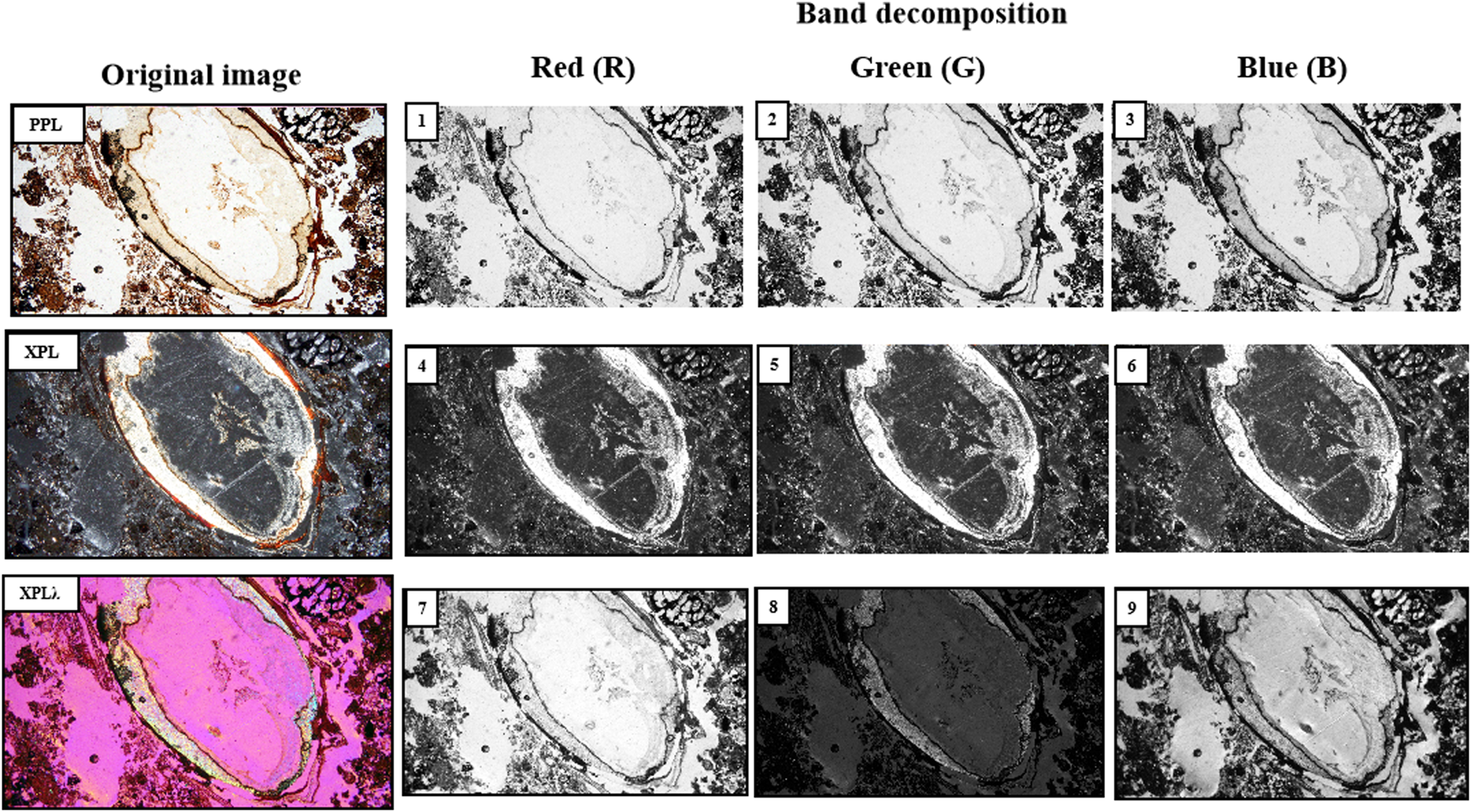
Light sources decomposition to obtain the bands (RBG). Image length 0.9 mm. PPL = Plain polarized light; XPL = Cross-polarized light; XPLλ = Cross-polarized light with gypsum compensator.
Data Collection and Classification
Of the total of the individual images obtained, four were selected that had the maximum representativeness of each class and the highest quality in their elaboration, i.e., no birefringence caused by strain in resin. Then, 20 training fields were created, each consisting of 100 points, giving a total of 2,000 training sites for all images (Figure 3). For each training site, the brightness values of each of the nine bands were obtained using the “Extract values by points” routine of ArcGIS v.10.3 software. (Environmental Systems Research Institute, 2015). Each training site with its respective brightness values was classified (A, B, C, D or P). The 2,000 points included mainly organic components; however, in some thin sections there were also inorganic components. Therefore, their removal was necessary to obtaining the organic material models. Consequently, a raster database was built with 1,511 points bearing 13,599 point-data.
FIGURE 3
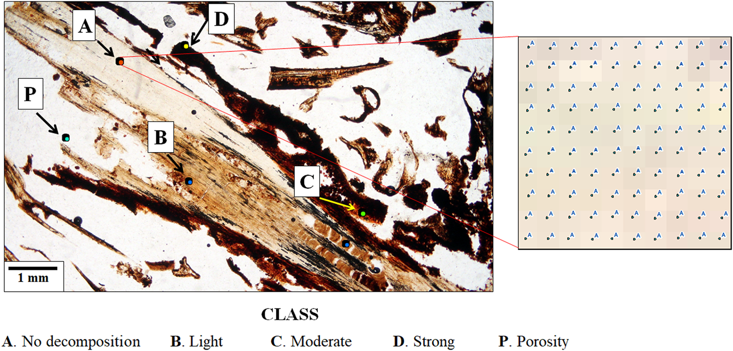
Location of training sites for the degrees of decomposition of organic matter. The arrows indicate the sampled points. The box on the right represents a site with 100 sampling pixels in PPL. The image corresponds to forest soil, Acrisols, Oaxaca, Mexico.
Dataset Preparation for Binary Classification
Five replicas of the original database were created to obtain the discriminant functions for binary classification, one for each level of decomposition and porosity. A cell reclassification was carried out in each database, which involved changing the class column; for example, Class A was changed to a value of 1 and the rest of the classes to values of 0 classes, producing binary classifications. Subsequently, the data set of each database was randomly divided into two: 80% to train the models and 20% to validate them according to the recommendations of James et al. (2013).
Separability between binary classes was performed using scatter diagrams with R version 3.5.3 (R Core Team, 2017) for each class analyzed, using the ggplot2 package. In addition, the minimum and maximum values of each class were evaluated to establish their ranges. If the scattergrams showed overlap between the binary classes, the points were reclassified and assigned values of 0; this process was called data cleaning, also known as data cleanse or data purge.
Linear Discriminant Analysis and Estimation of Accuracy
Linear discriminant analysis (LDA) was carried out on the training fields of each database, using R v.3.5.3 through the MASS (Modern Applied Statistics with S) package and resulting in nine coefficients. The highest brightness values were selected from these coefficients, and a constant and a centroid were generated for each equation. According to Brown (2000), centroids are the mean of the values of the group members in a given discriminant function.
Kappa coefficient criterion to assess the classification (user’s and producer’s accuracy) of the reliability of the models were used according to Story and Congalton (1986) and Jensen (2015) proposals. The confusion matrix was carried out using the predict and confusion matrix functions of the caret and lattice packages of R v.3.5.3.
Construction of Thematic Maps and Quantification of Organic Features
The discriminating functions were applied to the images from which training fields were obtained, the individual images, and the mosaics, all this to execute the validation process of such discriminant functions. This procedure was performed with the ArcGIS raster calculator v.10.3, in which the selected bands in the LDA were multiplied by the coefficients of the generated discriminant function. After running the models in ArcGIS, a raster map was obtained showing classes of varying degrees of organic matter decomposition.
Finally, the quantification of each class was carried out by obtaining the percentage of pixels with respect to the total image.
Results
Colour of the Degrees of Decomposition of Organic Matter
Figure 4 shows the representative colours of the five classes evaluated with different light sources, in which it can be observed that there is better separation of colours between PPL and XPLλ; while in XPL, there is confusion in three classes (C, D, and P) as a result of the isotropy of all materials. It is also shown that classes A, B, and D have some colour homogeneity regardless of light; class P contrasts in all light sources.
FIGURE 4
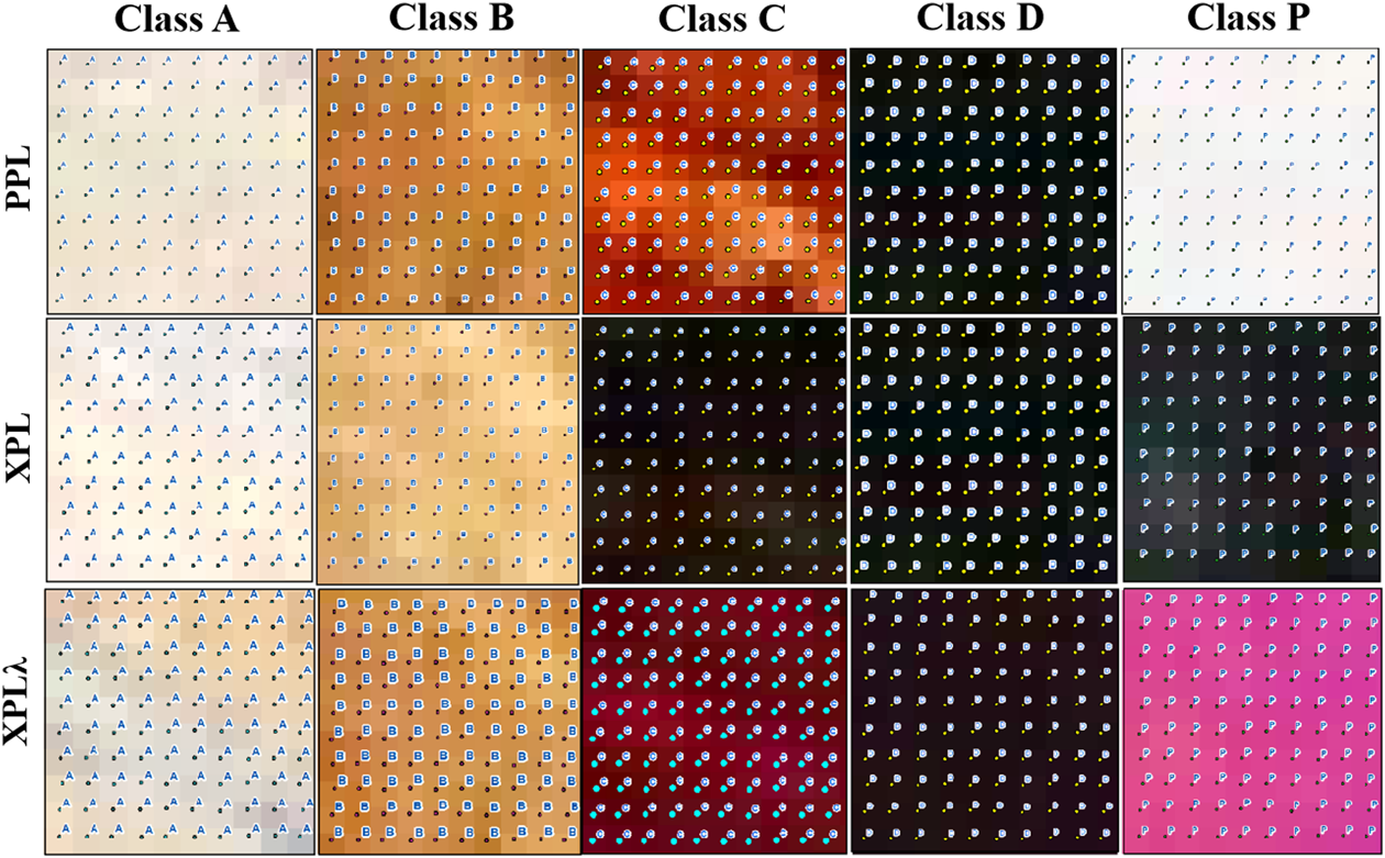
Representative colours of composite images (RGB format) of different light sources and each degree of decomposition of organic matter. (A) No decomposition; (B) Light; (C) Moderate; (D) Strong, and Porosity (P).
Degrees of Brightness
Figure 5 shows an overlap in brightness values between some classes when analyzing the original values, ranging from minimum (Class A, C, D, and P) to evident (Class B). However, with the re-categorization, the brightness values intervals were modified. For example, in class B, with less 30% modification, the brightness values of the intervals were reduced from 49 to 215 to 77–157 (green band in PPL) and from 17 to 177 to 17–79 (blue band in PPL) as it can be seen in Table 3.
FIGURE 5
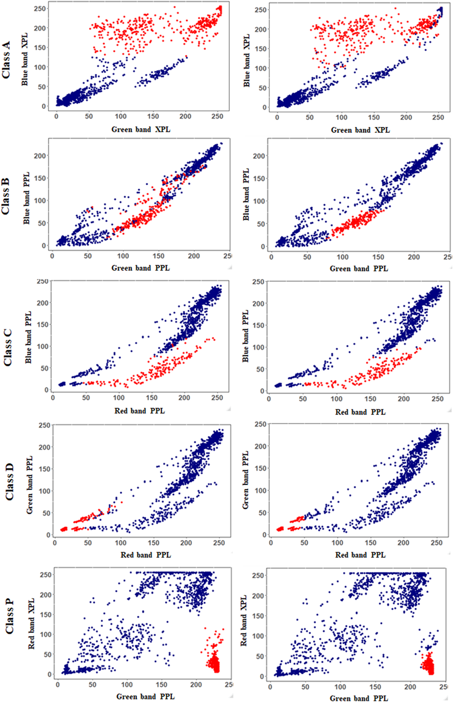
Scatter-plots of brightness values obtained in selected bands for each class. Left-hand column shows the classes without data cleaning and right-hand column the classes after the application of data cleaning. The highest point reduction is shown in class B. Red points represents the level of decomposition of interest.
TABLE 3
| Class | Bands/Light | Without cleaning data | Cleaning data | |||
|---|---|---|---|---|---|---|
| Training points | Brightness values | Training points | Brightness values | |||
| A. No decomposition | G | XPL | 476 | 52–255 | 476 | 52–255 |
| B | 102–255 | 102–255 | ||||
| B. Light | G | PPL | 301 | 49–215 | 203 | 77–157 |
| B | 17–177 | 17–79 | ||||
| C. Moderate | R | PPL | 88 | 46–210 | 79 | 46–210 |
| G | 6–117 | 6–82 | ||||
| B | 0–92 | 0–32 | ||||
| D. Strong | R | PPL | 176 | 9–101 | 153 | 9–73 |
| G | 9–74 | 9–49 | ||||
| P. Porosity | G | PPL | 370 | 207–239 | 343 | 207–239 |
| R | XPL | 5–115 | 5–58 | |||
Number of sampling points used (PDE) for each class and their intervals of brightness values for each band analyzed before and after of data cleaning.
Discriminant Functions
Each class studied with the linear discriminant analysis has specific lights and bands where the feature was characterized due to its increased sharpness and contrast (Table 4). For example, because by the type of light, the non-decomposed organic matter (Class A) stands out better in XPL (birefringence); whereas, the totally decomposed organic matter (Class D) is best identified (opacity and isotropy) in PPL. With XPLλ, the function coefficients obtained from LDA were low, and therefore were not further analysed.
TABLE 4
| Class/Degree | Light sources | Band | Discriminant function | Centroid | ||
|---|---|---|---|---|---|---|
| R | G | B | ||||
| A. No decomposition | XPL | * | * | (G*−0.01516403) + (B*0.04774093) −3.218647 | 0.8040 | |
| B. Light | PPL | * | * | (G*0.05868941) + (B*−0.06535330) −0.6480741 | 0.769385 | |
| C. Moderate | PPL | * | * | * | (R*−0.08307243) + (G*-0.16502634) + (B*0.07993119) −0.5141844 | 2.6354 |
| D. Strong | PPL | * | * | (R*−0.06047865) + (G*0.03148932) +6.758695 | 2.4631 | |
| P. Porosity | PPL | * | (G*0.03305831) + (R*0.02557389) | 1.3942 | ||
| XPL | * | −2.04559 (G*0.02653818) + (G*0.01991728) −1.660535 | ||||
Bands and light source used to generate the models for each level of decomposition evaluated. The information that is presented is derived from the data cleaning.
As for the bands, the green (G) is helpful for all classes, the blue (B) gives good results in classes A, B, and C (up to moderate decomposition) and the red (R) only in class D, when the organic matter (OM) is strongly decomposed. Of the nine original variables, only two or three bands of the PPL and XPL were used to generate the models.
Accuracy of Models
The overall accuracy of the models was greater than 94% for Class A, C, D, and P and 89.1% for Class B. The accuracy increased by almost 5% for Class A and up to 6% for Class B, when data cleanse is applied to the training data set (Table 5).
TABLE 5
| Class/Decomposition degree | Without cleaning data | Kappa Coef. | Cleaning data | Kappa Coef. | ||||
|---|---|---|---|---|---|---|---|---|
| Accuracy (%) | Accuracy (%) | |||||||
| Producer | User | Overall | Producer | User | Overall | |||
| A. No decomposition | 97.6 | 87.1 | 94.9 | 0.89 | 99.4 | 98.8 | 99.4 | 0.99 |
| B. Slightly decomposed | 75.9 | 70.7 | 89.1 | 0.66 | 99.1 | 68.2 | 93.9 | 0.78 |
| C. Moderately decomposed | 87.3 | 86.4 | 96.1 | 0.85 | 92.5 | 77.7 | 96.6 | 0.82 |
| D. Strongly decomposed | 100 | 77.9 | 96.7 | 0.86 | 100 | 73 | 96.2 | 0.82 |
| P. Porosity | 100 | 98.3 | 99.6 | 0.99 | 100 | 91.6 | 98.1 | 0.94 |
Overall, user’s and producer's accuracy as well as Kappa coefficient of models applied in the classification of decomposition of organic matter. These values were obtained from the initial data and after a cleaning process.
Producer´s accuracy was for classes A, B, and C of 97.6%, 75.9%, and 87.3%, respectively, and for class D and P of 100%. After cleaning the data, the accuracy was increased, especially for class B (>22%). However, in user´s accuracy, percentages were lower for all classes when compared to those obtained in producer’s (70.7%–98.3%); furthermore, after data cleansing, most percentages decreased (up to 8%), except for class A, which increased 11%.
The kappa coefficient obtained values ranged from 0.66 (Class B) to 0.99 (in the rest of the classes). After the data cleanse was applied, the values were irregular.
Application of the Model, Extraction of Features, and Creation of Thematic Maps
When the discriminant function was applied with the new pixel values, grayscale images were generated, where the class of interest was highlighted in a lighter shade compared to the other classes (Figure 6A). Subsequently, the layers were extracted (Figure 6B) and joined together to generate the thematic map of the different degrees of organic matter decomposition (Figure 6C).
FIGURE 6
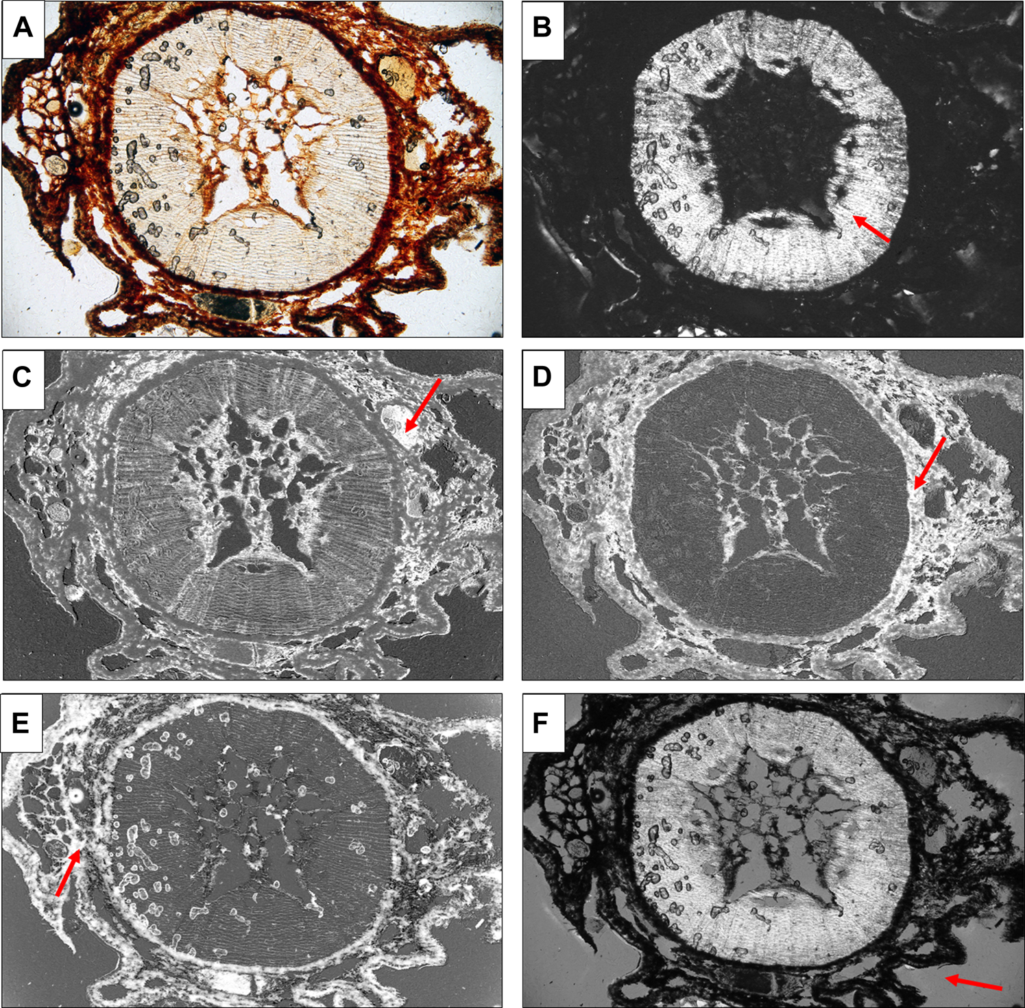
Application of linear models to identify the decomposition levels of organic matter, which shows a lighter colour (red arrows) than the rest of the components. (A) Original image in PPL, (B) No decomposition, (C) Light, (D) Moderate, (D) Strong, and (E) Porosity. In this last case the model creates a balance between PPL and XPL and generate the porous space appears gray. Frame length 5.5 mm. Andosols-Texcoco, Mexico.
Figure 7 shows the maps generated in individual images, and Figure 8 shows the maps constructed from high resolutions mosaics where it can be seen that there is no clear division in classes A and B (without slight decomposition).
FIGURE 7
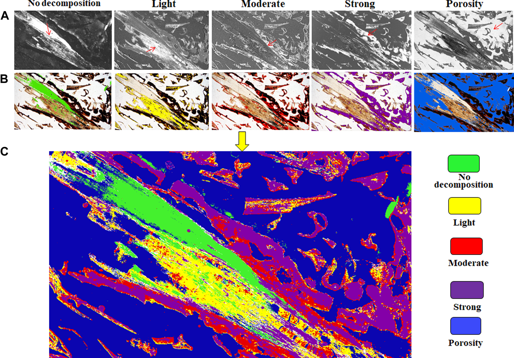
(A) Application of models and creation of thematic maps from individual images of thin sections of composting process. (B) Extraction of decomposition levels and (C) generation of thematic maps resulting from the union of the layers generated in the previous step. Frame length 9 mm.
FIGURE 8
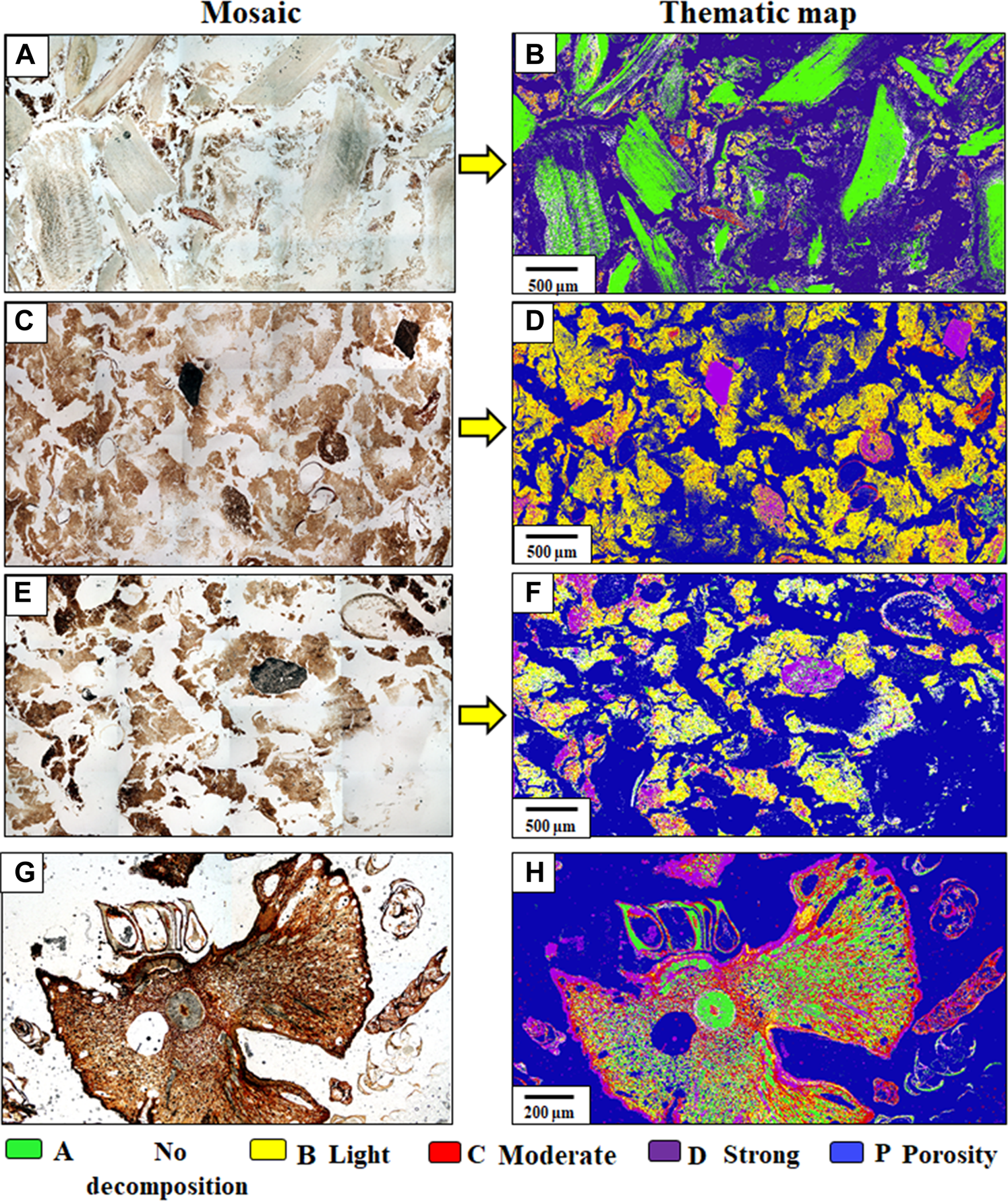
Application of decomposition models on thin sections of composting process and creation of thematic maps from high-resolution mosaics. (A,C,E,G) original mosaics; and (B,D,F,H) classified mosaics.
Quantification
The percentages of the objects classified in raster format agree with the visual analysis; however, in most training images, an overestimation was found in several classes as the percentages exceeded 100%. On the other hand, with the validation images, the percentages were less than 100% in most cases (Table 6).
TABLE 6
| Organic materials images | Class A | Class B | Class C | Class D | Class P | Total | |
|---|---|---|---|---|---|---|---|
| % | |||||||
| Training | 1. Cupressus6A (Forest) | 8.4 | 14.4 | 6.7 | 20.1 | 54.8 | 104.4 |
| 2. Humus (Forest) | 11.8 | 12.4 | 6 | 21.4 | 51.4 | 103 | |
| 3. Compost (Manure) | 22.7 | 8.7 | 3 | 17.4 | 56.4 | 108.2 | |
| 4. Organic amendments | 17.1 | 4 | 1.9 | 23.8 | 50.4 | 98.2 | |
| Validation | 5. Compost7B | 16.9 | 15 | 1 | 5.9 | 59 | 79.9 |
| 6. Compost7D | 22.7 | 17.5 | 1 | 6.4 | 38.7 | 86.6 | |
| 7. Compost7F | 7 | 9.1 | 11.3 | 10.2 | 59 | 96.6 | |
| 8. Compost7H | 30.7 | 9.2 | 1.7 | 6.1 | 38.2 | 85.9 | |
| 9. Mosaic8B | 26.6 | 3 | 1.5 | 0.7 | 63.9 | 95.7 | |
| 10. Mosaic8D | 4.3 | 44.5 | 5.1 | 5 | 52.3 | 111 | |
| 11. Mosaic8F | 3.1 | 13.1 | 2.5 | 5.4 | 64.5 | 85 | |
Quantification of decomposition levels of organic matter in training and validation images. The superscript indicates the figure from which the quantification was performed.
As mentioned above, a “subclass” was presented in the images, which could not be classified with this method. This subclass was identified as the transition between non-decomposed materials and those with slight decomposition. Therefore, if the percentages are below 100%, this class was present in the image.
Analysis of Thematic Maps
The resulting thematic maps (Figure 8) show the distribution at microscale, of the varying degrees of decomposition of organic matter in the topmost layers of several soils and composting materials. These maps only highlighted the organic feature, no other features were highlighted except for the void; therefore, no associations could be identified with other pedofeatures, at this present time. However, it is safe to assume that material with relatively higher degrees of composition were closer to the proximity of voids (Figures 8D,F), since these materials are more exposed to decomposing agents; in contrast to materials relatively farther from the voids, which presented lower degrees of decomposition. In addition, the distribution of these stages followed a gradual pattern, that is, classes A and B, or classes C and D, would cluster together more frequently (Figures 8B,D), than classes A and C or classes B and D (top right of Figure 7). The occurrences of clusters of class A with classes C and D can be explained as abrupt displacements of materials due to water flow or faunal activity. Finally, no inferences could be made between degrees of organic matter decomposition with size of voids, suggesting the decomposition process of organic occurs independently of the size of voids within the soil fabric.
Discussion
Data Collection and Classification
The extraction of brightness values directly from the raster images provided descriptive statistics that were used to determine class membership (Foody and Mathur, 2006). This procedure allows for direct analysis of the data and establishing degrees of decomposition of organic matter with an increased reliability.
The high-resolution images obtained in this research of just over 2,000,000 pixels in an individual image and up to 586,000,000 pixels in a ×2 mosaic make traditional sampling impractical (Congalton, 1991; Foody and Mathur, 2006). For example, Congalton (1988) suggested sampling 1% of the mapped area; however, this would mean a total of 20,000 pixels per category without considering that classes do not have the same representativeness in the images.
We found that the sampling intensity can be between 160 and 537 training pixels for each class. Congalton (1991) recommends using 50 pixels as the minimum number of units to perform classifications, while Mather (2004) suggests that 30 training pixels are helpful for each class regardless of each classification method. Aydemir et al. (2004) set a minimum of 100 points for each class to obtain the brightness values of the features evaluated on thin sections of soil.
It is essential to highlight that the expert knowledge used to generate the classification reduced the sampling intensity due to the choice of representative sites as significant features of interest for the proposed classes, as established by Lu and Weng (2007). This procedure allows the proper collection of data from the proposed categories and the correct class assignment to a pixel. Blamire (1996) mentions that differences in sampling intensity (training fields) are attributable to the representativeness of the class in the image and its complexity to be classified.
Degrees of Brightness
In the first stage of this research, the analysis of different degrees of decomposition is visual and qualitative; therefore, errors in classification are introduced by confusing the different shades of colour and the degree of membership of the pixels to the predetermined classes. For this reason, re-classification of data was convenient to increase the accuracy of the models and to achieve brightness intervals that better represented the decomposition levels of organic matter.
Data cleanse or properly referred as data purge decreased the values identified as non-distinctive within each class (Arai, 1992; Mather, 2004), and resulted in a more refined representation of classes (Foody and Mathur, 2006). In addition, data purge is necessary in quantitative research so as to bring data to a quality and reliability levels to be used for statistical modelling (Van der Loo and de Jonge, 2018).
As regards to the varying degrees of organic matter decomposition, Gutiérrez-Castorena et al. (2018) reported intervals that differ from those presented in this study. This is because the authors established three categories of degrees of decomposition (light, moderate, and strong) instead of four. And the image processing performed by these authors was more complex; therefore, the brightness values were different.
Optical Characteristics of Degrees of Organic Matter Decomposition and Their Relationship to Brightness Values
The brightness values showed overlap, mainly because of the nature of the decomposition of organic matter. The decomposition is a gradual process; therefore, transitions between different stages present abrupt or diffuse boundaries according to their optical properties in the different light sources (Bullock et al., 1985). Nonetheless, the overlapping intervals provide a general idea of how classes can be described and characterized (Marschallinger 1997; Adderley et al., 2002).
This criterion has been used by some authors, but for other soil components. For example, Adderley et al. (2002) determined the degrees of brightness of carbonates in each band of the XPL, where the feature of interest is best represented by its high birefringence, in what is called the “pure signature” (Gutiérrez-Castorena et al., 2018). This feature occurs in brightness values close to 255 in the red, green, and blue bands in XPL. This condition can be explained by two optical properties: contrast and sharpness, which are essential for establishing relationships between the feature of interest and the adjacent materials (Bullock et al., 1985; Stoops, 2003). Carbonates have prominent contrast and abrupt sharpness in XPL, a light source where the feature is enhanced (Bullock et al., 1985).
In the case of organic matter decomposition, materials without decomposition are better characterized in XPL caused by the high cellulose birefringence (Babel, 1975; Bullock et al., 1985; Stoops, 2003), with prominent contrast, and abrupt sharpness. The behaviour is similar in the class with high decomposition, but characterized in PPL, where the contrast is also sharp, and the colors are darker than any other level of decomposition (Bullock et al., 1985). Therefore, the identification of the light source is very important for the delimitation of the component based on its optical properties.
In class B, the sharpness is diffuse, and the contrast is faded, hence this class involves a critical transition, i.e. decrease its birefringence in XPL, which indicates the decomposition of the cellulose fibres (Babel, 1975) and present yellowish/brown colorations in PPL (Bullock et al., 1985; Stoops, 2003). This class was the most difficult to characterize and showed the most significant overlap during the classification process. Finally, it was impossible to characterize an intermediate “subclass” between class A and B, although more sampling sites were placed on the unclassified pixels. In this sense, this intermediate class deserves special attention and more exhaustive analysis to complete its characterization.
Finally, the porosity required two light sources for its extraction due to the similarity with the characteristics of some state of decomposition of the organic components. For example, highly decomposed organic material (Class D) and porous space are isotropic in XPL (Bullock et al., 1985), and some light brown tones of non-decomposed or lightly decomposed organic material can be confused on light intensity. Therefore, using two bands on two light sources creates a balance and dramatically enhances the feature. Gutiérrez-Castorena et al. (2018) found that porosity, in the case of Andosols, is better characterized by PPL and XPL because of the confusion caused by andic materials that present isotropic nature.
Linear Discriminant Analysis
The importance of creating models or discriminating functions of organic matter decomposition levels is that they can represent the process through mathematical relationships or equations (Motta and Pappalardo, 2012). Furthermore, when these models are applied to other new cases (images), automation of classification and quantification of decomposition levels becomes easier to carry out. An additional advantage of using the models is that the user does not necessarily have to be an expert in soil micromorphology since the discriminant functions have been previously created based on expert knowledge.
Some statistical methods have been used previously to analyze images of other soil components in thin sections. These routines include supervised and unsupervised classification (Tarquini and Favalli, 2010; Sauzet et al., 2017; Gutiérrez-Castorena et al., 2018), ANOVA (Brzychcy et al., 2012), and multivariate analysis such as that of principal components (Terribile et al., 1995; Jangorzo et al., 2014). Gutiérrez-Castorena et al. (2018) used the supervised and unsupervised classification in organic materials; however, the processing was complex and demanding in computational terms because map operators were carried out with the composite images, i.e., in their original color composition (RGB). Sugiyama, 2007 mention that separate bands allowed less information processing and computational time when performing image analysis.
Accuracy
Overall precision values obtained were very high (greater than 94%) for all cases because of the LDA’s robustness (Foody and Mathur, 2006). Additionally, the percentages obtained are comparable with other supervised grading methods previously used for thematic mapping in soil thin sections (Sauzet et al., 2017; Gutiérrez-Castorena et al., 2018).
In addition, producer’s accuracy increases significantly, both before and after applying data purge, which means that the omission error decreases; that is, a smaller number of pixels were not omitted from the class category. This statistic indicates how well a specific area can be mapped (Story and Congalton, 1986); however, when user’s accuracy is evaluated, the values are lower, especially when data cleanse is applied. This indicates that it increases the commission error, i.e., the probability that a pixel falls into one category and belongs to another.
According to Jensen (2015), kappa coefficient >0.80 represents a high agreement between the classification map and the reference information. Values between 0.4 and 0.8 represent a moderate agreement and <0.40 a poor/poor agreement. As a result, classes A, C, D and P show a high concordance and class B a moderate one. Even this is the same classification before applying data clean-up. According to previous statisticians, the discriminant functions generated in this research can classify the levels of organic matter decomposition into O horizons.
An important aspect to mention is that it is necessary to check the execution of the model visually. Consequently, validation through acquired knowledge or what is known as “expertise” is very important in micromorphological analysis and should even be considered as an additional criterion to numerical data (Mather, 1987). Hence, after the generation of a model and checking the accuracy, it was visually analyzed whether the classification was correct; in other words, it is a method that employs an expert system.
Application of the Model and Quantification
With the application of the model, new pixel values are generated, the images are improved, and the feature of interest is highlighted, while the rest of the components are opaque. The application of the model is fast because a “macro-model” can be built within the software, as a basis for adding bands of the new image. Therefore, there is no need to rewrite the entire process every time the image analysis for such a purpose is performed. Also, it is necessary to consider that this process is straightforward when there is a high quality of elaboration within the thin section (birefringence in porous space in XPL). An additional issue is when a pixel falls into two classes because the model can overestimate or underestimate the class area. The second case is attributed to the fact that a pixel with a not well defined membership may be more susceptible to fall into two classes when using a binary classification algorithm. An option to improve the separability between classes is the application of map algebra. In this routine, the layer with the highest representativeness serves as the basis for subtraction over the one that overlaps the class of interest. Protz and VandenBygaart (1998) applied this same technique in clayey coatings, which was obtained by subtracting pores and minerals.
Despite the difficulties mentioned above, discriminant functions can be applied to research aimed at assessing decomposition levels in the O horizon, in the O-A transition, or to composting materials, as a way to probe/explore the decomposition status of organic matter. The recommended routine is: photographing, decomposition of strips, application of models, and quantification. The user will also decide whether, apart from applying the models, other processes (such as map algebra) need to be carried out to eliminate class overlap, as described above.
Conclusion
The banding of the images obtained from different light sources of the petrographic microscope proved to be very useful for analyzing the brightness values associated with each level of decomposition of organic matter. Each level was related to one or two light sources (only PPL and XPL) and the combination of two or three bands.
The functions were generated using linear discriminant analysis to classify the degrees of organic matter decomposition with high precision. Furthermore, the application of the functions automated the creation of layers of the organic matter decomposition degrees of to create thematic maps.
Finally, this research represents a first approach to creating classification models in soil thin sections and may be helpful in the generation of more classification models for other soil components using different statistical methods.
Statements
Data availability statement
The original contributions presented in the study are included in the article/Supplementary Material, further inquiries can be directed to the corresponding author.
Author contributions
TG-V and MG-C writing and review of document, data collection, performing statistical analysis.
Funding
This research was supported by the Consejo Nacional de Ciencia y Tecnología (CONACYT) through the award number 283318.
Conflict of interest
The authors declare that the research was conducted in the absence of any commercial or financial relationships that could be construed as a potential conflict of interest.
References
1
Adderley W. P. Simpson I. A. Davidson D. A . Colour Description and Quantification in Mosaic Images of Soil Thin Sections. Geoderma (2002) 108(3):181–195. 10.1016/s0016-7061(02)00123-4
2
Arai K. A Supervised Thematic Mapper Classification with a Purification of Training Samples. Int. J. Remote Sensing (1992) 13(11):2039–2049. 10.1080/01431169208904251
3
Aydemir S. Keskin S. Drees L. R. Quantification of Soil Features Using Digital Image Processing (DIP) Techniques. Geoderma (2004) 119(1-2):1–8. 10.1016/S0016-7061(03)00218-0
4
Babel U. Micromorphology of Soil Organic Matter. In: GiesekingJ E., editor. Soil Components. Berlin, Heidelberg: Springer (1975). p. 369–473. 10.1007/978-3-642-65915-7_7
5
Blamire P. A . The Influence of Relative Sample Size in Training Artificial Neural Networks. Int. J. Remote Sensing (1996) 17(1):223–230. 10.1080/01431169608949000
6
Brown M. T. Wicker L. R . Discriminant Analysis. In: TinsleyH E., editor. Handbook of Applied Multivariate Statistics and Mathematical Modeling. San Diego: ElSevier Academic Press (2000). p. 209–235. 10.1016/b978-012691360-6/50009-4
7
Brzychcy S. Zagórski Z. Sieczko L. Kaczorek D. Analysis of Groundmass Color as a Tool for Evaluating the Extent of Pedogenic Processes in Chromic Soils. Soil Sci. Annu. (2012) 63(3):3–7. 10.2478/v10239-012-0026-z
8
Brzychcy S. Zagórski Z . Analysis of Groundmass Colour as a Tool for Evaluating the Extent of Pedogenic Processes in Chromic Soils. 3rd ed. New Jersey: Prentice-Hall (2010).
9
Bullock P. Fedoroff N. Jongerius A. Stoops G. Tursina T. Babel U . Handbook for Soil Thin Section Description. Wolverhampton: Waine Research Publications (1985).
10
Congalton R. G . A Comparison of Sampling Schemes Used in Generating Error Matrices for Assessing the Accuracy of Maps Generated from Remotely Sensed Data. Photogramm. Eng. Remote Sensing. (1988) 54(5):593–600.
11
Congalton R. G. A Review of Assessing the Accuracy of Classifications of Remotely Sensed Data. Remote Sensing Environ. (1991) 37(1):35–46. 10.1016/0034-4257(91)90048-B
12
Environmental Systems Research Institute. ArcGis 10.3 Computer Software. Redlands, CA: Environmental Systems Research Institute Inc (2015).
13
Fanning D. S. Fanning M. C. B. Soil: Morphology, Genesis and Classification. New York: John Wiley & Sons (1989).
14
Foody G. M. Mathur A. The Use of Small Training Sets Containing Mixed Pixels for Accurate Hard Image Classification: Training on Mixed Spectral Responses for Classification by a SVM. Remote Sensing Environ. (2006) 103(2):179–189. 10.1016/j.rse.2006.04.001
15
Gutiérrez-Castorena M. C. Gutiérrez-Castorena E. V. González-Vargas T. Ortiz-Solorio C. A. Suástegui-Méndez E. Cajuste-Bontemps L. et al Thematic Micro-maps of Soil Components Using High-Resolution Spatially Referenced Mosaics from Whole Soil Thin Sections and Image Analysis. Eur. J. Soil Sci. (2018) 69(2):217–231. 10.1111/ejss.12506
16
Hallinan J. S . Data Mining for Microbiologists. In: HarwoodC.WipatA., editors. Methods in Microbiology. Cambridge, MA, USA: Academic Press (2012). p. 27–79. 10.1016/b978-0-08-099387-4.00002-8
17
James G. Witten D. Hastie T. Tibshirani R . An Introduction to Statistical Learning with Applications in R. New York: Springer-Verlag (2013).
18
Jangorzo N. S. Schwartz C. Watteu F . Image Analysis of Soil Thin Sections for a Non Destructive Quantification of Aggregation in Early Stages of Pedogenesis. Eur. J. Soil Sci. (2014) 65(4):5485–5498. 10.1111/ejss.12110
19
Jensen J. R . Introductory Digital Image Processing. A Remote Sensing Perspective. 4th ed. USA: Pearson (2015).
20
Lu D. Weng Q . A Survey of Image Classification Methods and Techniques for Improving Classification Performance. Int. J. Remote Sensing (2007) 28(5):823–870. 10.1080/01431160600746456
21
Marschallinger R . Automatic mineral Classification in the Macroscopic Scale. Comput. Geosciences (1997) 23(1):119–126. 10.1016/s0098-3004(96)00074-x
22
Mather P. M . Computer Processing of Remotely-Sensed Images. An Introduction. 3rd ed. Chichester: John Wiley & Sons (2004).
23
Mather P. M . Computing Processing of Remotely-Sensed Images: An Introduction. New York: John Wiley (1987).
24
Mika S. Ratsch G. Weston J. Schölkopf B. Müller K. B . Fisher Discriminant Analysis with Kernels. In: HuY HLarsenJWilsonEDouglasD S, editors. Neural Networks for Signal Processing IX. Madison, USA: IEEE (1999). p. 41–48. 10.1109/NNSP.1999.788121
25
Motta S. Pappalardo F . Mathematical Modeling of Biological Systems. Brief. Bioinform. (2012) 14(4):411–422. 10.1093/bib/bbs061
26
Poch R. M. Micromorfometría. In: LoaizaJ C.StoopsG.PochR M.CasamitjanaM, editors. Manual de Micromorfología de suelos y técnicas complementarias. Medellin: Fondo Editorial Pascual Bravo (2015). p. 293–302.
27
Protz R. Shipitalo M. J. Mermut A. R. Fox C. A . Image Analysis of Soils - Present and Future. Geoderma (1987) 40(1-2):115–125. 10.1016/0016-7061(87)90017-6
28
Protz R. Sweeney S. Fox C . An Application of Spectral Image-Analysis to Soil Micromorphology. 1. Methods of Analysis. Geoderma (1992) 53(3-4):275–287. 10.1016/0016-7061(92)90059-G
29
Protz R. VandenBygaart A. J. Towards Systematic Image Analysis in the Study of Soil Micromorphology. Sci. Soils. (1998) 3(1):34–44. 10.1007/s10112-998-0004-0
30
R Core Team. R: A Language and Environment for Statistical Computing. Vienna, Austria: R Foundation for Statistical Computing (2017). Available at: https://www.R-project.org/.
31
Ringrose-Voase A. Micromorphology of Soil Structure - Description, Quantification, Application. Soil Res. (1991) 29(6):777–813. 10.1071/SR9910777
32
Sauzet O. Cammas C. Gilliot J. M. Bajard M. Montagne D . Development of a Novel Image Analysis Procedure to Quantify Biological Porosity and Illuvial clay in Large Soil Thin Sections. Geoderma (2017) 292:135–148. 10.1016/j.geoderma.2017.01.004
33
Skvortsova E. B. Sanzharova S. I. Micromorphometric Features of Pore Space in the Plow Horizons of Loamy Soils. Eurasian Soil Sci. (2007) 40(4):445–455. 10.1134/S1064229307040114
34
Stoops G. Guidelines for Analysis and Description of Soil and Regolith Thin Sections. Wisconsin: Soil Science Society of America (2003).
35
Story M. Congalton R. G. Accuracy Assessment: A User´s Perspective. Photogramm. Eng. Remote Sensing. (1986) 52(3):397–399.
36
Sugiyama M. Dimensionality Reduction of Multimodal Labeled Data by Local Fisher Discriminant Analysis. J. Mach. Learn. Res. (2007) 8(37):1027–1061.
37
Taina I. A. Heck R. J. Utilization of Object-Oriented Software in the Image Analysis of Soil Thin Sections. Soil Sci. Soc. Am. J. (2010) 74(5):1670–1681. 10.2136/sssaj2008.0359
38
Tarquini S. Favalli M . A Microscopic Information System (MIS) for Petrographic Analysis. Comput. Geosciences (2010) 36(5):665–674. 10.1016/j.cageo.2009.09.017
39
Terribile F. Fitzpatrick E. A . The Application of Some Image-Analysis Techniques to Recognition of Soil Micromorphological Features. Eur. J. Soil Sci. (1995) 46(1):29–45. 10.1111/j.1365-2389.1995.tb01810.x
40
Terribile F. Wright R. Fitzpatrick E. A . Image Analysis in Soil Micromorphology: From Univariate Approach to Multivariate Solution. In: ShobaS.GerasimovaM.MiedemaR., editors. Soil Micromorphology: Studies on Soil Diversity, Diagnostics, Dynamics. Wageningen: Printing Service Centre Van Gils (1997). p. 397–417. (Moscow-Wageningen: Proc. Int. Working Meet on Soil Micromorphology 10th).
41
Van der Loo M. de Jonge E . Statistical Data Cleaning with Applications in R”. New York: John Wiley & Sons (2018).
42
Zech W. Guggenbergeri G. Lehmannr J. Miltnero A. Schroth G. Miltner A. et al Factors Controlling Humification and Mineralization of Soil Organic Matter in the Tropics. Geoderma (1997) 79:117–161. 10.1016/S0016-7061(97)00040-2
Summary
Keywords
linear discriminant analysis, micromorphometry, thematic maps, supervised training, variable selection
Citation
González-Vargas T and Gutiérrez-Castorena MDC (2022) Brightness Values-Based Discriminant Functions for Classification of Degrees of Organic Matter Decomposition in Soil Thin Sections. Span. J. Soil Sci. 12:10348. doi: 10.3389/sjss.2022.10348
Received
07 January 2022
Accepted
04 April 2022
Published
12 May 2022
Volume
12 - 2022
Edited by
Michele Louise Francis, Stellenbosch University, South Africa
Updates
Copyright
© 2022 González-Vargas and Gutiérrez-Castorena.
This is an open-access article distributed under the terms of the Creative Commons Attribution License (CC BY). The use, distribution or reproduction in other forums is permitted, provided the original author(s) and the copyright owner(s) are credited and that the original publication in this journal is cited, in accordance with accepted academic practice. No use, distribution or reproduction is permitted which does not comply with these terms.
*Correspondence: Ma Del Carmen Gutiérrez-Castorena, castor@colpos.mx
Disclaimer
All claims expressed in this article are solely those of the authors and do not necessarily represent those of their affiliated organizations, or those of the publisher, the editors and the reviewers. Any product that may be evaluated in this article or claim that may be made by its manufacturer is not guaranteed or endorsed by the publisher.