Abstract
The development of Urban Air Mobility (UAM) has led to the introduction of various electric vertical takeoff and landing (eVTOL) aircraft configurations, which plays a crucial role in determining performance. This paper systematically compares two typical eVTOL configurations, lift + cruise and tiltrotor, under the context of a UAM mission with a payload of 200 kg and a range of 200 km. Employing a comprehensive aircraft sizing and mission analysis framework, the study evaluates weight, energy consumption, power requirements, and noise characteristics. The results show that the tiltrotor outperforms the lift + cruise in terms of maximum takeoff weight (MTOW), cruise aerodynamic efficiency, and mission energy consumption, mainly due to the avoidance of non-operating lift systems during cruise, thus reducing aerodynamic and weight penalties. However, the tiltrotor presents increased complexity in propulsion system design and mode transition. Noise analysis highlights that the lift + cruise generates significantly higher sound pressure levels (SPL) during vertical takeoff and landing (VTOL) due to high disk loading rotors, posing a critical urban constraint. A sensitivity analysis of battery energy density indicates that, although improvements in energy density enhance overall performance for both configurations, the relative performance gap remains stable across various energy densities. Ultimately, the configuration type plays a dominant role in determining aircraft performance. This study provides quantitative insights for eVTOL configuration selection and early-stage UAM aircraft design.
Introduction
Electric Vertical Takeoff and Landing (eVTOL) aircraft are pivotal to the advancement of Urban Air Mobility (UAM), offering significant advantages, including the elimination of runways, low noise levels, and zero carbon emissions. Distributed Electric Propulsion (DEP) provides substantial design flexibility for aerodynamic layouts, enabling a broad spectrum of innovative configurations for eVTOL [–]. Despite these advantages, the main challenge for fully electric systems remains low battery energy density, which severely restricts range and payload capacity [].
To facilitate UAM’s realization, NASA has spearheaded several conceptual design studies, establishing foundational models and performance data for mission analysis and evaluations [–]. Several studies have explored eVTOL mission performance, focusing on the sensitivity of key design parameters—such as rotor size, wing loading, and battery energy density—to mission outcomes like range, payload, and speed [–]. These efforts provide systematic frameworks for configuration optimization and trade-off analysis. Literature [–] focuses on typical configurations lift + cruise, tiltrotor, and Tiltwing, offering internal design explorations and preliminary design feasibility assessments for each.
This paper investigates the performance of the lift + cruise and tiltrotor configurations, developed by NASA, using an aircraft sizing and mission analysis framework. The focus is on key performance metrics such as weight, energy consumption, and noise, with an additional sensitivity analysis on battery energy density. This study aims to offer guidance for configuration selection and early-stage design decisions in eVTOL development.
Methodology
The overall methodology is structured around a systematic approach to eVTOL aircraft sizing and mission analysis, as illustrated in Figure 1.
FIGURE 1
Configuration and geometry sizing rules
In this study, two representative eVTOL configurations developed by NASA—the lift + cruise [] and the tiltrotor []—are selected as the reference aircrafts for comparative analysis. Geometry sizing is conducted while maintaining target wing loading and disk loading, reflecting aircraft performance during both the cruise and VTOL phases. These parameters govern geometry adjustments throughout the sizing iterations, where the wing area is adjusted to sustain the target wing loading, while the aspect ratio, taper ratio, and trailing edge angle are kept constant. Tail size is adjusted using a fixed tail volume coefficient, based on the main wing area and fuselage length. Rotor size is determined by disk loading and MTOW, calculating the total required disk area, which is then used to determine the rotor radius.
Aerodynamics
The aerodynamic analysis is based on the methods proposed in []. Vortex lattice method (VLM) is employed to compute the wing lift. Parasite drag is evaluated through a component buildup approach, where the viscous drag of individual components is calculated using skin friction based models with form factor corrections and then summed in an area-weighted manner. Induced drag is derived from the lift distribution predicted by the vortex lattice solution, with an additional lift-dependent viscous correction. The total drag is constructed by combining parasite and induced contributions within a unified aerodynamic buildup framework []. The aerodynamic methods have been validated in the literature for conceptual aircraft analysis [].
Propulsion system architecture
Figure 2 illustrates the architecture of the all-electric propulsion system, which is powered by batteries that supply electrical energy to the aircraft’s motors. The motors drive the rotors, with a battery capacity constraint ensuring that at least 20% of the battery’s capacity remains after completing a typical mission. The performance parameters for the electric propulsion system components are sourced from the literature [–]. While the efficiency of the propulsion system varies with operating conditions, a representative efficiency value is chosen for this study, reflecting typical mission conditions. The rotor performance such as thrust coefficient, power coefficient and efficiency is solved using XROTOR [], a rapid solver for rotor aerodynamics based on blade element-vortex theory, which enables quick and reasonably accurate calculation of rotor performance.
FIGURE 2
Weight estimation
The aircraft mass is estimated using a physics-based weight buildup method [], adapted from the Airbus A3 Vahana conceptual study [26]. The approach is load-driven rather than regression-based, making it suitable for novel eVTOL configurations without historical statistical data. Structural components, including the wing, fuselage, and rotors, are sized according to limit load conditions and material strength constraints under prescribed safety factors. Propulsion and electrical system masses are determined based on maximum thrust requirements and transmitted power levels.
Mission analysis
The mission profile is divided into two distinct phases: VTOL mode (hover, vertical climb, transition, and vertical descent) and fixed-wing flight mode (accelerated climb, and cruise). A simplified model estimates the required power for each flight mode. Hover power [27] is calculated as Equation 1:where represents the thrust, is the air density, is the number of rotors, is rotor figure of merit calculated using XROTOR and is the disk area. For the transition phase, power consumption is assumed to remain constant, averaging the starting and ending power values (Equation 2) [27]:where is the hover power, is the transition power and is the power reduction factor.
In fixed-wing flight mode, the power is estimated using the lift-to-drag ratio () (Equation 3):where is total mass of the vehicle is gravitational acceleration is cruise velocity is efficiency of the electric powertrain and is propeller efficiency calculated using XROTOR.
The study uses the Fourth-Order Runge-Kutta method (RK4) for numerical integration, iterating through the following steps to solve the system at each time step (Equation 4):where is new value of the state variable at the next time step is current value of the state variable, is time step is intermediate calculations for the Runge-Kutta method and the is the function evaluation at each step. The RK4 method is applied to time-varying state variables, such as the aircraft’s altitude and energy consumption.
Noise model
Rotors are the dominant noise sources of eVTOL aircraft. This study accounts for harmonic and broadband noise contributions. Harmonic noise is primarily generated by the periodic motion of the blades and consists of thickness noise and loading noise. The prediction is based on the rotor aeroacoustic formulations developed by Hanson [28] and Farassat [29]. The sound pressure fluctuations associated with the m-th harmonic order are calculated using Bessel functions and azimuth angle corrections. The total harmonic acoustic pressure is integrated over the blade span, yielding the total SPL according to Equation 5:where is harmonic sound pressure and is reference sound pressure.
Broadband noise mainly arises from the interaction between the turbulent boundary layer and the blade trailing edge. In this study, the trailing-edge noise model proposed by Li et al. [30] is adopted. The total sound pressure level is obtained by energetic superposition of the harmonic and broadband components (Equation 6):where is broadband sound pressure level and is total sound pressure level.
The implementation details and validation basis of the present aeroacoustic framework follow Clarke [], in which the harmonic, broadband, and isolated rotor noise predictions were validated against published experimental data. Finally, an A-weighting filter is applied to account for human auditory frequency sensitivity. In this study, the acoustic observer is located at a distance of 36 ft from the rotor axis, which is adopted as a near-field reference location commonly used in rotor aeroacoustic studies []. In addition, the rotor tip mach number is limited to 0.65 to avoid excessive compressibility effects and to suppress high-speed impulsive noise.
Results and analysis
Mission
The aircraft sizing process begins with defining the mission profile and associated requirements. The sizing mission profile, based on NASA’s research on UAM missions [31], is illustrated in Figure 3.
FIGURE 3
The target payload and cruise speed are specified as 200 kg and 234 km·h-1, respectively. The takeoff altitude is assumed to be 1800 m above mean sea level, while the cruise altitude is set to 1,200 m above ground level. During VTOL operations, the aircraft operates under nominal conditions with a vertical climb rate of 2.5 m·s-1. In the fixed-wing flight regime, the climb segment is modeled using a constant climb flight-path angle of 5°. A detailed summary of the mission requirements is provided in Table 1.
TABLE 1
| Category | Requirement |
|---|---|
| Payload | 200 kg |
| Mission range | 200 km |
| Cruise speed | 234 km·h-1 |
| Takeoff altitude | 1800 m mean sea level |
| Cruise altitude | 1,200 m above ground level |
| Climb rate at VTOL mode | 2.5 m·s-1 for normal operating conditions |
| Climb flight-path angle | 5° |
Mission requirements.
Configurational trade study
Based on the results illustrated in Table 2 and Figures 4–8, a systematic configurational trade study is conducted to compare the lift + cruise and tiltrotor eVTOL configurations under identical UAM mission requirements. This comparison focuses on differences in aircraft weight distribution, energy efficiency, key design parameters, and acoustic performance.
TABLE 2
| Configuration | 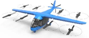 | 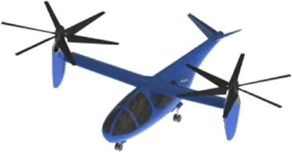 |
|---|---|---|
| MTOW | 1,013 kg | 964 kg |
| Empty (% of MTOW) | 813.2 kg (80%) | 763.7 kg (79%) |
| Structure (% of MTOW) | 313.4 kg (31%) | 277.4 kg (29%) |
| Battery (% of MTOW) | 317.1 kg (31%) | 289.9 kg (30%) |
| Payload (% of MTOW) | 200.0 kg (20%) | 200.0 kg (21%) |
| Propulsion (% of MTOW) | 182.7 kg (18%) | 196.4 kg (20%) |
| Power-to-weight ratio | 2.87 kW·kg-1 | 3.36 kW·kg-1 |
| Rotor diameter | 1.59 m | 3.29 m |
| FOM | 0.79 | 0.84 |
| Cruise L/D | 10.96 | 11.68 |
| Wing area | 6.96 m2 | 6.58 m2 |
| Mission energy consumption | 75.70 kWh | 68.68 kWh |
| SPL | 92 dB | 69 dB |
Comparison for lift + cruise and tiltrotor eVTOL configurations.
Quantitatively, the overall weight breakdown of the two configurations shows broadly similar proportions across major subsystems, as illustrated in Figure 4. However, the tiltrotor achieves a lower MTOW (964 kg) compared to the lift + cruise (1,013 kg), resulting in a reduction of approximately 4.8%. This difference is primarily attributed to the fact that, in the lift + cruise, the vertical lift system—including lift rotors and supporting booms—becomes inactive dead weight during cruise, contributing additional parasite drag. The aerodynamic performance comparison under cruise conditions is shown in Figure 5, where the L/D trends indicate superior cruise efficiency for the tiltrotor configuration. The analysis was conducted at an altitude of 3,000 m, with a speed range of 0.1–0.3 Mach, and an angle of attack ranging from 0° to 10°. The lower cruise efficiency of the lift + cruise increases thrust and energy demand for the same mission.
FIGURE 4
FIGURE 5
In terms of mission energy consumption, the lift + cruise requires 75.7 kWh to complete the 200 km mission, whereas the tiltrotor requires 68.7 kWh, representing an energy reduction of approximately 9.3%. The higher energy requirement of the lift + cruise necessitates a larger battery mass, which in turn increases the MTOW, creating a positive feedback loop between energy requirement, aircraft weight, and thrust.
At the propulsion system level, both configurations exhibit distinct engineering trade-offs. The tiltrotor employs fewer but significantly larger rotors (3.29 m in diameter vs. 1.59 m for the lift + cruise), with a figure of merit (FOM) of 0.84, compared to 0.79 for lift + cruise. The rotor performance was analyzed at an altitude of 3,000 m and a cruise speed of 234 km·h-1, with varying advance ratios under cruise conditions is presented in Figure 6. Under one-engine-inoperative (OEI) conditions, each tiltrotor must bear a higher load and provide greater redundancy, necessitating more robust blade and drivetrain designs. Consequently, the propulsion system accounts for a slightly higher fraction of MTOW (20% vs. 18%). In contrast, the lift + cruise achieves greater system redundancy through eight lift rotors, reducing the structural burden on individual rotors and enhancing fault tolerance.
FIGURE 6
The noise analysis reveals significant differences in acoustic performance between the two configurations. The acoustic directivity and harmonic–broadband composition are presented in Figure 7. The lift + cruise exhibits a sound pressure level (SPL) of 92 dB at a 45° observer location, notably higher than the 69 dB predicted for the tiltrotor. This disparity is primarily due to the high disk-loading rotors in the lift + cruise, which generate strong harmonic noise during VTOL operations, while broadband noise contributions remain relatively modest. Without dedicated acoustic optimization, the noise levels of the lift + cruise significantly exceed typical residential noise limits for urban air mobility (<67 dB) [32], posing a critical constraint for urban deployment.
FIGURE 7
Figure 8 presents the payload–range characteristics of the two configurations. Both curves exhibit an approximately linear trade-off, reflecting the energy-limited nature of fully electric propulsion, where increased range requires battery mass to replace payload under a fixed structural mass and usable energy constraint. At the 200 km design point, the two curves intersect. The slope of each curve is governed by the cruise energy consumption per unit distance. Owing to its higher aerodynamic efficiency, the tiltrotor requires less additional battery mass per unit range, resulting in a shallower slope and 2%–3% greater maximum range. For shorter ranges (<200 km), the tiltrotor shows slightly lower payload capacity due to its higher propulsion mass fraction and smaller baseline battery mass. Overall, the lift + cruise is more suitable for short-range missions, while the tiltrotor is advantageous for medium-to long-range operations.
FIGURE 8
Overall, the tiltrotor demonstrates superior performance in terms of aerodynamic efficiency, MTOW, mission energy consumption, and acoustic characteristics. However, its increased configurational complexity—particularly associated with rotor tilting mechanisms, mode transitions, and aeromechanical coupling—poses higher engineering challenges. Conversely, the lift + cruise offers a simpler structural and control architecture with higher inherent redundancy, but suffers from penalties in aerodynamic efficiency and noise performance. Therefore, the selection of an appropriate configuration must be guided by specific mission requirements and operational scenarios.
Sensitivity studies
To evaluate the impact of battery technology advancement on the performance of different eVTOL configurations, a sensitivity study is conducted by varying the battery energy density from 300 Wh·kg-1 to 700 Wh·kg-1. As illustrated in Figures 9–11, increasing battery energy density leads to a pronounced reduction in MTOW, mission energy consumption, and characteristic power requirements for both configurations. The trends are particularly significant in the lower energy-density range (300–400 Wh·kg-1), indicating a strong sensitivity of aircraft performance to battery energy density in this regime.
FIGURE 9
FIGURE 10
FIGURE 11
For the lift + cruise, the MTOW is reduced by approximately 37% over the considered energy-density range, while the tiltrotor exhibits a slightly larger reduction of approximately 40%. In both cases, the battery mass fraction decreases substantially with increasing energy density. Specifically, the battery mass fraction of the lift + cruise decreases from approximately 31%–15% of MTOW, while that of the tiltrotor decreases from 30% to 14%. This increase in battery energy density effectively reduces the battery mass required to complete the mission, thereby lowering the overall aircraft weight and further decreasing power requirements and mission energy consumption in a positive feedback loop.
Within the energy-density range of 300–700 Wh·kg-1, the total mission energy consumption of the lift + cruise and tiltrotor decreases by approximately 32% and 36%, respectively. Higher battery energy density enables a substantial reduction in the required system power level, with the maximum power requirement decreasing by approximately 37% for the lift + cruise and 40% for the tiltrotor configuration.
Despite these absolute improvements, the differences in mission energy consumption, power and MTOW between the two configurations remain relatively constant across the entire energy-density range. This indicates that the inherent aerodynamic efficiency and system integration characteristics of each configuration are the primary factors governing overall performance, rather than the absolute level of battery technology.
In the higher energy-density regime (600–700 Wh·kg-1), the rate of power reduction gradually diminishes. This trend suggests that once battery energy density is no longer the primary limiting factor, system power requirements become increasingly constrained by other factors, including the aerodynamic efficiency limits of the rotor and wing, propulsion system efficiency, and inherent disk loading and aerodynamic layout characteristics of each configuration. Consequently, the marginal performance gains achievable solely through further increases in battery energy density are expected to diminish, and future performance improvements will increasingly rely on configuration optimization, aerodynamic refinement, and enhancements in propulsion system efficiency.
Overall, the sensitivity analysis confirms that battery energy density is a crucial factor influencing eVTOL aircraft weight, mission energy consumption, and power requirements for both configurations. Although both configurations exhibit similar sensitivity to changes in battery energy density, the differences in MTOW, energy consumption, and power requirements attributable to configuration characteristics remain relatively stable across the energy-density range. At higher energy densities, the system’s performance shifts from being primarily energy-limited to being constrained by aerodynamic and configurational factors.
Conclusion
This study provides a quantitative comparison of the lift + cruise and tiltrotor eVTOL configurations for a representative UAM mission (200 kg payload, 200 km range) using an integrated aircraft sizing and mission analysis framework.
The results demonstrate that the tiltrotor offers clear advantages in maximum takeoff weight, cruise aerodynamic efficiency, mission energy consumption, and acoustic performance, primarily because it eliminates the dead-weight and parasite-drag penalties associated with non-operating lift systems during cruise. However, these benefits come at the cost of higher engineering complexity in rotor tilting mechanisms and mode transition control. The noise analysis identifies disk loading as the critical acoustic driver during VTOL operations, with the lift + cruise exceeding typical urban noise limits by a substantial margin.
The sensitivity study confirms that advances in battery energy density benefit both configurations similarly, but the performance gap between them remains stable across the full energy-density range examined (300–700 Wh·kg-1), indicating that configuration architecture is the dominant determinant of overall performance rather than battery technology alone. At high energy densities, system performance shifts from being energy-limited to being constrained by aerodynamic and configurational factors.
In summary, the tiltrotor is preferable for range- and noise-sensitive UAM missions, while the lift + cruise is better suited to short-range operations where mechanical simplicity and redundancy are prioritized. Future work should incorporate higher-fidelity aeroacoustic and aerodynamic models, and address rotor–wing interaction, propulsion–airframe co-optimization, and real urban noise propagation to extend these findings to a broader design space.
Statements
Data availability statement
The original contributions presented in the study are included in the article/supplementary material, further inquiries can be directed to the corresponding author.
Author contributions
XC: Conceptualization, writing – original draft, writing – review and editing. XY: Writing – review and editing. YM: Writing – review and editing. YL: Conceptualization, writing – review and editing. YZ: Writing – review and editing. All authors contributed to the article and approved the submitted version.
Funding
The author(s) declared that financial support was received for this work and/or its publication. This work was supported by the Fundamental Research Funds for the Central Universities under Grant No. 226-2024-00031.
Conflict of interest
The author(s) declared that this work was conducted in the absence of any commercial or financial relationships that could be construed as a potential conflict of interest.
Generative AI statement
The author(s) declared that generative AI was not used in the creation of this manuscript.
Any alternative text (alt text) provided alongside figures in this article has been generated by Frontiers with the support of artificial intelligence and reasonable efforts have been made to ensure accuracy, including review by the authors wherever possible. If you identify any issues, please contact us.
References
1.
EVE (2026). Mobility reimagined. Available online at: https://eveairmobility.com (Accessed May 11, 2026).
2.
AeroW (2026). Autonomous urban air mobility. Available online at: https://wisk.aero/aircraft (Accessed May 11, 2026).
3.
JobyA (2026). Joby. Available online at: https://www.jobyaviation.com (Accessed May 11, 2026).
4.
Vertical Aerospace (2026). VX4 - urban air mobility - vertical aerospace. Available online at: https://vertical-aerospace.com/vx4 (Accessed May 11, 2026).
5.
Lilium (2026). Lilium jet - the first electric VTOL (eVTOL) jet. Available online at: https://lilium.com/jet (Accessed November 12, 2022).
6.
Volocopter (2026). Volocopter. Available online at: https://www.volocopter.com (Accessed May 11, 2026).
7.
Jaunt Air Mobility (2026). Jaunt air mobility. Available online at: https://www.jauntairmobility.com (Accessed May 11, 2026).
8.
SilvaCJohnsonWRSolisEPattersonMDAntcliffKR. VTOL urban air mobility concept aircrafts for technology development. In: 2018 aviation technology, integration, and operations conference. American Institute of Aeronautics and Astronautics (2018). 10.2514/6.2018-3847
9.
WhitesideSKSPollardBPAntcliffKRZawodnyNZFeiXSilvaCet alDesign of a tiltwing concept vehicle for urban air mobility (2021). NASA TM-20210017971, Hampton, VA.
10.
WhitesideSKSPollardBP. Conceptual design of a tiltduct reference vehicle for urban air mobility. San Jose, CA: VFS Aeromechanics for Advanced Vertical Flight Technical Meeting, Vertical Flight Society (2022).
11.
RadotichM. Conceptual design of a tiltrotor aircraft for urban air mobility. In: VFS aeromechanics for advanced vertical flight technical meeting, vertical flight society. San Jose, CA (2022). p. 25–7.
12.
DuffyMJWakayamaSRHuppR. A study in reducing the cost of vertical flight with electric propulsion, AIAA 2017-3442. In: 17th AIAA aviation technology, integration, and operations conference (2017). 10.2514/6.2017-3442
13.
BrownAHarrisWL. A aircraft design and optimization model for On-Demand aviation (2018). 10.2514/6.2018-0105
14.
KadhiresanARDuffyMJ. Conceptual design and mission analysis for eVTOL urban air mobility flight aircraft configurations, AIAA 2019-2873. AIAA Aviation 2019 Forum (2019). 10.2514/6.2019-2873
15.
BacchiniACestinoE. Electric VTOL configurations comparison. Aerospace (2019) 6(3):26. 10.3390/aerospace6030026
16.
BhandariRChakrabortyI. Sizing and optimization of multi eVTOL configuration for urban air mobility applications, AIAA 2025-1434. Reston, VA:AIAA SCITECH 2025 Forum (2025). 10.2514/6.2025-1434
17.
ChakrabortyIMishraAA. Sizing and analysis of a lift-plus-cruise aircraft with electrified propulsion. J Aircraft (2023) 60(3):747–65. 10.2514/1.C037044
18.
WangSPereiraLTLRagniD. Design exploration of UAM aircrafts. Aerospace Sci Technol (2025) 160:110058. 10.1016/j.ast.2025.110058
19.
ChakrabortyIMillerNSMishraAA. Sizing and analysis of a tilt-wing aircraft with all-electric and hybrid-electric propulsion systems. In: AIAA SciTech 2022 Forum, AIAA Paper 2022-1515 (2022). 10.2514/6.2022-1515
20.
LukaczykTWWendorffADColonnoMEconomonTDAlonsoJJOrraTHet alSUAVE: an open-source environment for multi-fidelity conceptual aircraft design. In: AIAA 2015-3087.16th AIAA/ISSMO multidisciplinary analysis and optimization conference (2015). 10.2514/6.2015-3087
21.
ClarkeMA. Towards a regional and urban air mobility future: the development of computational approaches for quantifying trade-offs in electric aircraft design. Stanford university, department of aeronautics and astronautics. Thesis Ph.D. stanford university (2022). Available online at: https://purl.stanford.edu/xw679hn7192 (Accessed May 11, 2026).
22.
LentsC. Design of electrified aircraft propulsion system component modeling. In: AIAA SCITECH 2019. Reston, VA:AIAA Paper (2019).
23.
Electric Propulsion Components with High Power Densities for Aviation. Transformative vertical flight workshop. Munich, Germany:Siemens (2015).
24.
ZhaoXYangWSunZLiuYLiuW. Overview of electric propulsion motor research for EVTOL. Eng Proc (2024) 80(46):46. 10.3390/engproc2024080046
25.
DrelaMYoungrenH. XROTOR user guide (2003).
26.
BowerG. Vahana configuration trade study—part II,” Airbus A3 blog (2017). Available online at: https://acubed.airbus.com/blog/vahana/vahana-configuration-trade-study-part-ii/ (Accessed March, 2026).
27.
NathenP. Architectural performance assessment of an electric vertical take-off and landing (e-VTOL) aircraft based on a ducted vectored thrust concept (2018).
28.
HansonDB. Helicoidal surface theory for harmonic noise of rotors in the far field. AIAA J (1980) 18:1213–20. 10.2514/3.50873
29.
FarassatF. Linear acoustic formulas for calculation of rotating blade noise. AIAA J (1981) 19:1122–30. 10.2514/3.60051
30.
LiSLeeS. Prediction of urban air mobility multirotor VTOL broadband noise using UCD-QuietFly. J Am Helicopter Soc (2021) 66(3), 1–13. 10.4050/JAHS.66.032004
31.
PattersonMDAntcliffKRKohlmanLW. A proposed approach to studying urban air mobility missions including an initial exploration of mission requirements. In: Proc. AHS int. 74th annu. Forum technol. Display (2018). p. 1–19. 10.4050/F-0074-2018-12671
32.
HoldenJGoelN. Fast-Forwarding to a future of On-Demand urban air transportation (2016).White Paper, Uber.
Summary
Keywords
aircraft design, configuration comparison, electric propulsion, electric VTOL, lift + cruise
Citation
Chen X, Yao X, Man Y, Liu Y and Zheng Y (2026) Electric VTOL design exploration and configurations comparison for urban air mobility. Aerosp. Res. Commun. 4:16513. doi: 10.3389/arc.2026.16513
Received
03 March 2026
Revised
09 April 2026
Accepted
01 May 2026
Published
18 May 2026
Volume
4 - 2026
Updates
Copyright
© 2026 Chen, Yao, Man, Liu and Zheng.
This is an open-access article distributed under the terms of the Creative Commons Attribution License (CC BY). The use, distribution or reproduction in other forums is permitted, provided the original author(s) and the copyright owner(s) are credited and that the original publication in this journal is cited, in accordance with accepted academic practice. No use, distribution or reproduction is permitted which does not comply with these terms.
*Correspondence: Yaolong Liu, liuyaolong@zju.edu.cn
Disclaimer
All claims expressed in this article are solely those of the authors and do not necessarily represent those of their affiliated organizations, or those of the publisher, the editors and the reviewers. Any product that may be evaluated in this article or claim that may be made by its manufacturer is not guaranteed or endorsed by the publisher.