Abstract
Recent developments in commercial off-the-shelf flight controllers have paved the way for designing various Ground Control Stations (GCSs). However, these lack flight dynamics control integration. Integrating flight dynamics is necessary to incorporate correct aerodynamics and performance data for effective flight. This article presents a GCS application that enables sustained performance with various COTS controllers. AeroQT is a lightweight Qt framework-based application capable of executing software-in-the-loop and hardware-in-the-loop (HITL) simulations, along with real-flight testing for any aircraft, by integrating MAVLink messages in the same runtime application in which JSBSim and other custom features, such as autopilot modes, obstacle avoidance, and adaptive control (among others), are executed. In this approach, the MAVLink implementation was written in C++ using the MAVLink v2 C++ library for the transmission of sensor and actuator data between AeroQT and Pixhawk. In HITL mode, JSBSim (an open-source flight dynamics modeller) computes the desired actuator response, and MAVLink sends these actuator messages to PX4. With access to both real-time (Via MAVLink) and simulation sensor data (Via JSBSim UDP), AeroQT acts as a comprehensive test bench application for MAVLink-based flight controllers.
Introduction
In recent years, flight and autopilot testing algorithms have improved significantly with the advent of modern tools such as MATLAB [1], with which a Flight Dynamics Model (FDM) can be designed for a specific aircraft. There are several other simulation platforms, such as the Robot Operating System (ROS), Microsoft Flight Simulator, and Simulink toolboxes, for crafting FDMs. ROS and MATLAB have long been used professionally as a means of providing high-fidelity simulations in the field of robotics and aviation because they have extensive modelling tools and libraries available, and their ability to design Graphical User Interfaces (GUIs) makes these two frameworks an equitable choice for aircraft simulations. MATLAB can also be equipped with an open-source flight visualisation tool, i.e., FlightGear, via a Universal Data Protocol (UDP) connection, eliminating the need to build a separate Graphical User Interface (GUI) [1]. Recently, MAVLink was added to MATLAB as part of the Unmanned Aerial Vehicle (UAV) toolbox to aid in communication with MAVLink-based flight controllers. Similarly, MAVROS, a package provided in ROS, is a communication driver for messages between ROS nodes and PX4. It is also capable of message forwarding, which is used when a flight controller is connected to a companion board or to communicate with other flight controllers in a swarm-based application. However, MATLAB/Simulink suffers from poor performance and requires high computational power to visualise effective results.
A similar open-source 6-Degree-of-Freedom (DoF) FDM, JSBSim, is being utilised in the aerospace industry for the purpose of conducting Hardware-in-The-Loop (HITL) and Software-in-The-Loop (SITL) simulations, as it is capable of simulating a variety of aircraft configured in XML format [2]. As it is written in C++, it has become convenient for engineers to use its Standard Template Library (STL), a library of containers such as vector classes that act as arrays and can be called upon, including the FDMExec header file. JSBSim has proved to be a better-performing tool for flight testing because of its ability to execute several standalone instances simultaneously. As an open-source project, it has many contributors and developers who are continuously optimising it for efficient real-time simulations.
Zonggang Zhang et al. [3] developed a HITL platform by integrating PX4 with RPi 4, which was used for autopilot algorithms, swarm capability and communication between controllers. Although QGround Control (QGC) is capable of conducting HITL simulations, this approach had to utilise a companion board due to the limited availability of autopilot modes in the Ground Control Station (GCS) (e.g., QGC). Recently developed software, jMAVSim, accelerates the simulations with MAVLink-based flight controllers and provides a GUI interface for the visualisation of the JSBSim FDM. It can also forward messages from PX4 to GCS via the UDP protocol. This study utilised jMAVSim as a separate application to manage MAVLink messages and forward them further to QGC. Zongtong Luo et al. [4] utilised PX4 with RPi for an underwater vehicle and used MAVProxy for message forwarding and QGC as a control station. QGC, being customisable and open source, does not aid engineers to customise it to introduce their vehicle frame, control surfaces and sensors. Developers will need to access the PX4 firmware or QGC to calibrate the sensors and set control limits for the actuators.
Zhenhua Jiang [5] also made use of JSBSim and ROS tools to execute SWARM-based HITL simulation. He also integrated an FPGA to conduct complex computational modules for dynamic simulation and data communication via different protocols to achieve rapid control response. SA Hangal [6] formulated a framework using JSBSim and Python-based interfaces, which also included MAVProxy for communication, while criticising the inability of Simulink-based simulations to achieve a high-fidelity response. The majority of the researchers are dependent on MATLAB to test aircraft performance because Simulink provides a toolbox to facilitate the testing [7]. Simulink Realtime is a rapid prototyping toolset that aids HITL testing with a single click. F. Prochazka [8] deployed the compiled code from Simulink to an FPGA for real-time simulation, and he also utilised X-Plane for UAV motion. Gazebo has also been gaining popularity within the global drone community due to its large user base. Also, it can be integrated with ROS. In the study by Parker [9], testing of a fixed-wing aircraft landing on a moving target was conducted in a Gazebo environment, with different control schemes employed, such as MPC, LQR and PID. The developer had to create a model for each simulation component considered that could affect UAV motion (i.e., gravitational model, wind, Gusts and Turbulence, Ground effect, among others). Many MAVLink-based drones are validated in SITL and HITL simulations. These systems simulate real-world scenarios to test the robustness of the control algorithms in various conditions [10].
Recent studies have not focused sufficiently on the development of a universal testing platform or application for MAVLink-based flight controllers, which are primarily used in small, low-powered aircraft. Such a platform would only require a single application to be run on the device, and since FDM is designed via an XML file, it can also be executed as an instance in the same runtime in which MAVLink parsing is being performed. Nonetheless, this would greatly reduce the complexity of understanding UDP and MAVLink protocols, along with the need for multiple windows or terminals in the background, thus shifting the focal point of engineers and developers towards effectively building and testing their aircraft with customised autopilot modes and other control schemes. However, there should also be an element to develop understanding and implementation of MAVLink for an optimised and robust Input Output (IO) interface. For visualisation and characteristics, a Qt-based panel will provide sufficient information regarding the flight’s attitude, Primary Flight Display (PFD) and different tabs for navigation and autopilot purposes. However, a sufficient knowledge of C++ and object-orientated programming (OOP) is not required when operating the “AeroQT” platform, as it is designed for application purposes and serves as a standalone application for GCS controls.
Various features of different other GCSs are compared with AeroQT in Table 1.
TABLE 1
| Feature/Tool | QGroundControl (QGC) | Mission planner | MAVProxy | AeroQT (proposed) |
|---|---|---|---|---|
| Primary purpose | Mission planning and flight operations | Mission planning and telemetry | Command-line GCS and scripting | Lightweight MAVLink testing and autopilot evaluation |
| Installation and setup | Requires dependencies, multiple configurations | Windows-based, heavier setup | Requires Python scripting and a terminal | Single stand-alone executable, minimal setup |
| MAVLink handling | Yes (full protocol support) | Yes | Yes | Yes, integrated parser with a simplified interface |
| Flight dynamics modelling (FDM) | External simulator required (SITL, Gazebo, JSBSim) | External simulator required | External simulator required | Built-in FDM via XML, runs in the same runtime |
| Visualisation | Rich UI, PFD, maps | Rich UI, telemetry plots | Limited CLI output | Qt-based PFD, navigation and autopilot tabs |
| User skill requirement | Moderate (configuration, setup) | Beginner–intermediate | Advanced (command line, scripting) | Beginner-friendly, no coding required |
| Customisation focus | Mission planning and GUI | Mission planning | Protocol testing and scripts | Autopilot mode development, I/O evaluation |
| Target use case | Field operations, mission control | Field operations | Research, scripting automation | Research, development, and testing of MAVLink autopilot logic |
Summarises the differences between AeroQT and existing tools, highlighting its unique role as a lightweight MAVLink testing and evaluation platform.
Table 1 makes it visually clear that AeroQT is not competing with GCS software in field operations but rather filling the gap for lightweight MAVLink testing focused on research and development with built-in FDM support.
Methods
To acknowledge the functionalities of the AeroQT testing platform, the discussion will be based on the schematic diagram in Figure 1. A concept of nested executables (i.e., an executable within an executable) is implemented, which eliminates the requirement of additional terminal windows to run alongside the main application, i.e., QTJsbsim. The main executable is a Qt-based GUI application comprising capabilities such as visualisation of various sensor data received from either JSBSim or PX4 via a UDP port, various autopilot algorithms and execution of JSBSim as a shared library. Designing within the Qt framework eases the development process because of the variety of its libraries, classes, interactive GUI design, widget-based applications, cross-platform development and an intuitive code editor/debugger.
FIGURE 1

Overall functionality of the application.
Figure 1 illustrates the overall data flow of AeroQT as an interface between JSBSim (FDM), Pixhawk (autopilot hardware), and control modules. Sensor data from JSBSim (SITL/HITL) or Pixhawk is sent to AeroQT, which manages communication via UDP/TCP ports, device settings, and XML configuration files for sensors and actuators. AeroQT initiates MAVLink communication by parsing the incoming data and sending the actuator commands. The autopilot system (including vertical speed, heading, yaw damper, and manual control) then processes the sensor data and feeds back control signals, which are transmitted through AeroQT to either JSBSim or Pixhawk, thus completing the simulation or hardware-in-the-loop control loop.
AeroQT: Nested Executable
The schematic diagram shown in Figure 1 shows a node of the.ini file that initiates the additional executable and certain functionalities for communication and predetermining the aircraft type and their trim positions. Working within the Qt framework lets us utilise ‘QProcess’ to start external programs and ensure effective communication with them. To extract the information from the.ini file, the QSettings class allows for portable operations on certain file formats, along with managing application arguments and configurations. Once these numbers of arguments are stored in a QString array, they can be fed into QProcess to start the other application as a standalone executable or a separate process.
The standalone process started by QProcess has two types of arguments: MAVLink communication and JSBSim initialisation. MAVLink requires serial communication with devices, and JSBSim requires sufficient arguments to initiate the runtime simulation. However, this process must have a data flow control mechanism to avoid overflow and loss. “Chrono” is a part of the C++ Standard Library and can be used to implement data rate control. Selecting and testing an adequate data rate for the runtime application involves considering factors such as network bandwidth, latency requirements, and the means of data transmission. The data rate has a proportional relation with the device baud rate, which is usually 921,600 for USB connections and 57,600/115,200 for telemetry connections. PX4 sensors have different transmission rates, with the Inertial Measurement Unit (IMU) and magnetometer often having a high data rate ranging from tens to hundreds of hertz. The adjustment may require an iterative task, but the MAVLink acknowledge message can be utilised for this purpose by measuring the time interval between the commands sent and received by PX4.
JSBSim as a Shared Library
JSBSim is an open-source FDM that can be modified to include custom dynamic parameters such as moments, inertia, accelerations and position, which are then processed by nonlinear aircraft equations of motion. A minimalist, lightweight version of JSBSim was built by reducing certain features, such as propulsion models, complex aerodynamics, and unnecessary aircraft components (e.g., hydraulics and pneumatics), to reduce the computational load. JSBSim is also capable of generating dynamic link libraries, also known as shared libraries, which can be loaded and linked at runtime by the program “Bridge_executable”. This library contains the compiled JSBSim code used by the application to enable realistic flight simulation. By linking the shared library, the application also gains access to a set of header files in which JSBSim functions and classes are contained. FGFDMExec.h (Flight Dynamics Model Executive) is an important header to include in the project for accessing the “FGFDMExec” class, which manages and is responsible for coordinating various components in the simulation, including aircraft systems, setting component paths, control inputs, and more. The schematic in Figure 2 shows the SITL to HITL interconnection for JSBSim.
FIGURE 2
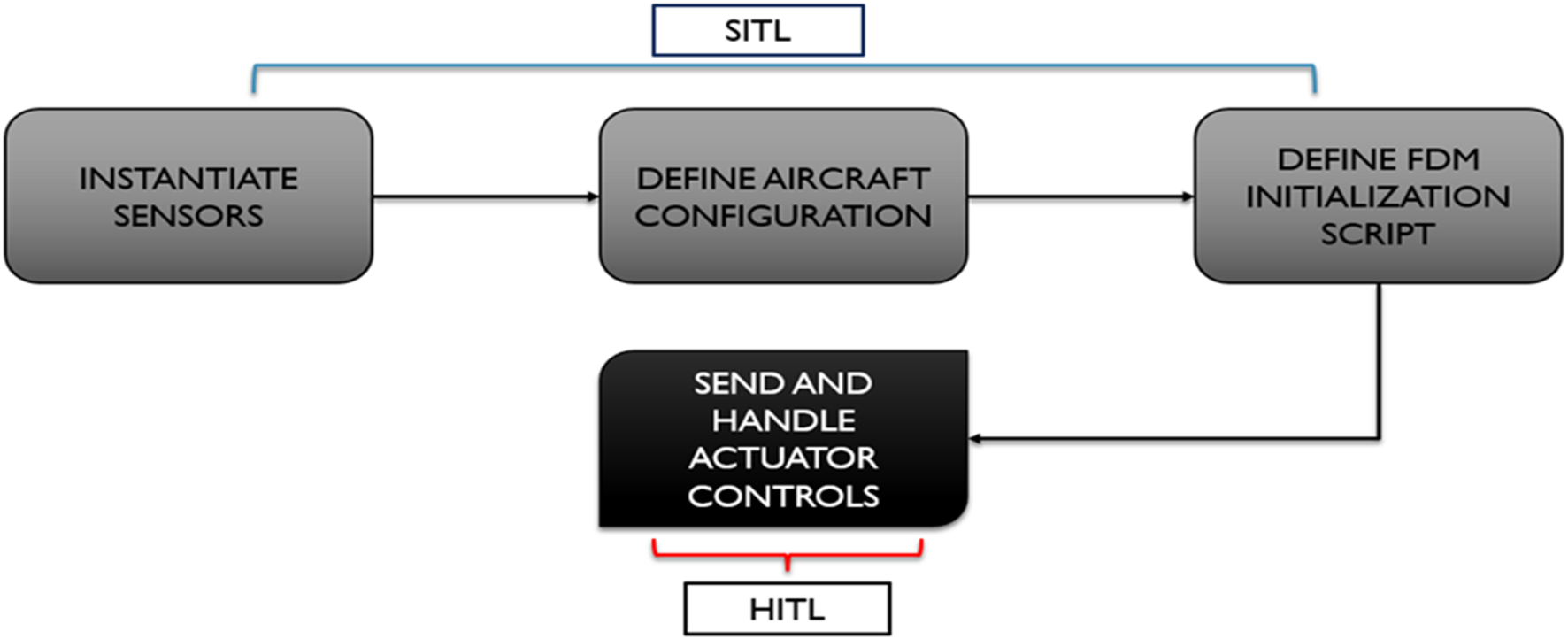
SITL and HITL workaround with JSBSim.
Networking With JSBSim I/O Ports
While JSBSim is a standalone FDM and provides support for a shared library, it can be integrated into a runtime application by defining native nodes in XML files and using them for information exchange between programs. UDP, which is known to be a lightweight protocol, is used to facilitate communication for real-time data transmission.
The output channel configuration on localhost at port 5138 with a rate of 10 Hz is specified as follows:
<output name=“localhost” type=“SOCKET” protocol=“UDP” port=“5138” rate=“10”>
<!-- List of output properties -->
</output>
These output property nodes will then be read by QTJSBSim as inputs to visualise the simulation outputs, such as aircraft position, attitude, velocity, propulsion data and more, representing various aspects of state and performance.
The functionality of the output socket is utilised to communicate across applications via a locally defined UDP port. As discussed in Section Networking With JSBSim I/O Ports, sensor nodes defined in XML have read and write capabilities using the GetPropertyValue or SetPropertyValue functions. The Bridge_executable reads data from PX4 over MAVLink serially and emits it on these property nodes. The sample format for setting a value for a node in C++ is as follows:
FDMExecPointer->SetPropertyValue(“pixhawk/sensor/sample”,variable_data_from_px4);
At the application end, the Qt framework provides various functionalities to manage the data emitted by JSBSim through output socket 5138, one of which utilises the QUdpSocket class to read the UDP datagrams. This involves binding to an address and port, followed by reading the datagrams to transfer the data. Property node values are stored in a QByteArray, which then can be separated into their respective fields for successful parsing of incoming data.
The block of code that follows configures an input channel on port 5139 with a rate of 10 Hz:
<input port=“5139” type=“QTJSBSIM” rate=“20”>
<!-- List of input properties -->
</input>
In the context of real flight testing and HITL, the input port is utilised as a means to transmit the actuator response from the Qt-based GUI panel to a list of respective property nodes. QTJSBSim has the role of packing control and command data into a specific format and transmitting it to the relevant destination node via UDP. The Bridge_Executable will then read these property values by using GetPropertyValue and send them to PX4 via MAVLink. The following is sample code for reading data from property nodes in C++:
Data_send_PX4=FDMExecPointer->GetPropertyValue(“pixhawk/sample_node”);
Definition of Sensors and Actuators in XML Format
The XML format for defining sensors and actuators represents a configuration file designed for creating JSBSim property nodes. The file is structured with a root element that defines the system, and it contains various components and properties for the runtime application. These properties include parameters related to angles, arming status, airspeed, battery status, and acceleration along different axes. The component breakdown is shown in Figure 3.
FIGURE 3
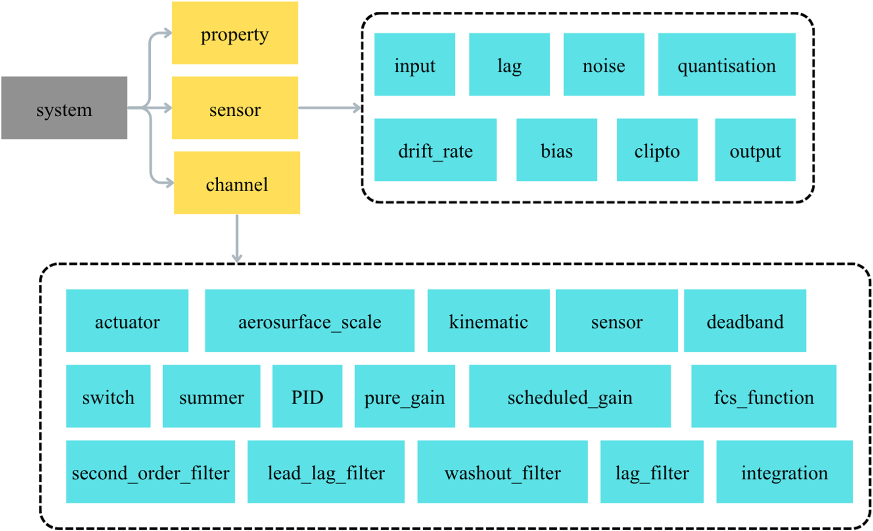
System components overview [11].
In JSBSim, an open-source Flight Dynamics Model (FDM), sensors and actuators are defined in the aircraft’s XML configuration files to simulate specific aspects of an aircraft’s systems.
Sensors
Definition: Sensors in JSBSim emulate the behaviour of real-world aircraft sensors by providing data (e.g., position, velocity, and altitude) with optional noise and biases. These are used for navigation, guidance, or feedback control systems in simulations.
Purpose: To mimic real-world sensor behaviour, including inaccuracies such as delays, biases, and noise.
XML Representation: Sensors are defined under the <sensors> tag in the aircraft file.
Actuators
Definition: Actuators simulate physical devices that control the aircraft based on inputs, such as control surfaces (e.g., ailerons and rudders) or engine power.
Purpose: To apply forces or moments to the aircraft model based on inputs, with optional modelling of delays or mechanical limits.
XML Representation: Actuators are defined under the <actuators> tag in the aircraft file.
MAVLink Implementation
MAVLink is a lightweight communication protocol designed for unmanned systems, known for its efficiency and compactness. Its minimal data overhead, use of a binary protocol, compact message format, customisability, and fixed message length all contribute to its lightweight nature. By incorporating error-checking mechanisms, MAVLink ensures data integrity while minimising latency in transmission. This protocol is adjustable to numerous communication channels, which makes it suitable for resource-constrained unmanned systems where efficient data exchange is crucial for reliable and efficient operation. The functionality of MAVLink is shown in Figure 4.
FIGURE 4
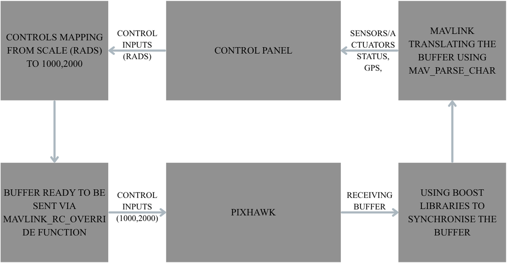
Functionality of MAVLink implementation.
The process of entangling MAVLink in the runtime application is crucial for conducting Hardware-in-the-Loop (HITL) simulation testing and incorporating the application with actual flight-testing capabilities. The C++ MAVLink library has been utilised for embedded communication with flight controllers, either serially or via a radio telemetry link. These messages are serialised into a binary format before transmission and deserialised upon receipt. The MAVLink library provides functions for serialising C++ message objects into a byte stream and deserialising byte streams into C++ objects. The inclusion of an appropriate MAVLink header is necessary to make these objects accessible in the application. On the Flight Control Unit (FCU) side, these incoming messages are dispatched to the relevant handlers based on the message’s ID and type. The following is sample code for sending a MAVLink packet from a control station application to a flight controller:
mavlink_rc_channels_override_t rc_override; //Msg to override rc channels
mavlink_message_t msg_rc; //instantiate mavlink message to be sent as a packet
rc_override.chan1_raw=aileron; // Aileron Channel sending data to aileron servo
rc_override.chan2_raw=elevator; // Elevator Channel sending data to elevator servo
rc_override.chan3_raw=throttle ;// Throttle Channel sending data to BLDC motor
rc_override.chan4_raw=rudder;//Rudder Channel sending data to rudder servo
rc_override.chan5_raw=0; // Extra ports
rc_override.target_system=1;//Send command to MAV 001
rc_override.target_component=1;//PX_COMP_ID_ALL; mavlink_msg_rc_channels_override_encode(1, 0, &msg_rc, &rc_override);
send_mavlink_message(&msg_rc);
Prior to sending and receiving data from the flight controller, asynchronous serial communication is established using the “boost.Asio” library for smooth data transmission. A complete approach for implementing a MAVLink bridge between the control station and the flight controller relies on various elements and should be discussed in detail.
Serial Communication
A serial connection is required between the application and Pixhawk at a certain baud rate for transmitting the MAVLink buffer from Pixhawk to the application and vice versa. Boost-Asio contains a class named “serial_port” for communicating with portable serial devices. When connected via USB, the device name is set to “ttyACM0,” which is the default port through which Pixhawk communicates in case of HITL. When connected via telemetry, the device name is set to “ttyUSBn” where “n” depends on the port to which the telemetry receiver device is attached (n = 0,1,2,3). Connectivity via USB is always important for calibrating servos and sensors during the pre-flight phase.
When configuring serial ports using Boost. Asio library, it is important to set the device parameters such as start or stop bits, parity bits, and flow control to none because MAVLink, as a protocol, does not use traditional start and stop bits such as those found in standard serial communication protocols such as Universal Asynchronous Receiver-Transmitter (UART). Instead, MAVLink relies on a fixed baud rate for communication and uses a message-based format that includes message framing and checksums for error checking and synchronisation.
Data Translation
Data translation with MAVLink is a critical part of integrating sensors, devices, or software components into MAVLink-based systems, allowing proper communication and buffer transmission within the system. When a device is opened with an application with no overflow in receiving and transmitting data, the next stage is to encode and decode the outgoing and incoming buffers, which contain MAVLink messages in the form of packets. Error handling should be implemented to manage cases where decoding fails or where message integrity checks are not passed. This process is repeated for each MAVLink message type relevant to the application.
Encoding the Outgoing Buffer
In this setup, only actuator data and arming commands are transmitted because mission commands are not necessary due to the application’s integration with autopilot modes. Before sending messages to the Pixhawk controller, the application must identify itself as a control station using MAVLink heartbeat messages to ensure communication with the correct system ID. Heartbeat messages consist of vehicle type, component ID and the version of the MAVLink protocol used by the application.
The aircraft features four control surfaces: two ailerons, a rudder, and an elevator, each driven by a servo, along with a Brushless Direct Current (BLDC) motor for thrust control. A custom airframe for our aircraft can be introduced in the PX4 firmware, but the aircraft used for testing already has a matching airframe, MAV_ODID_UA_TYPE_AEROPLANE, which fulfils the control surface requirements.
Since only one vehicle is used on the MAVLink channel, the system ID will be set to “1.” To send information, broadcasting messages to all components of the receiving system is necessary, and for this purpose, the component ID is set to MAV_COMP_ID_ALL, which allows access to all onboard and offboard components of Pixhawk.
The struct is now ready to be sent to Pixhawk using the encode function from the heartbeat MAVLink library:
mavlink_msg_heartbeat_encode(‘ID of this system’, ‘ID of this component (e.g. 200 for IMU)’, ‘The MAVLink message to compress the data into’, ‘C-struct to read the message contents from’)
Decoding the Incoming Buffer
In order to receive information from the Pixhawk, such as sensor and servo status, either via USB or telemetry, a translation of the buffer is required. This information is stored in an array and parsed in a loop twice the size of the received buffer to avoid noisy data. However, it is not recommended to use loops in communication bridges; the maximum buffer size (MAVLINK_MAX_PACKET_LEN) is limited to a few bytes, so it will not create delays when sending and receiving messages. The maximum MAVLink message length can be 280 bytes, so our loop will execute for 280 iterations. This method of parsing the MAVLink buffer is taken from MAVROS, which executes a loop on the received buffer up to the size of the received bytes.
The mavlink_parse_char function in the mavlink_helpers header file is used to parse the incoming packet. The function parses the data 1 byte at a time, returning 0 (MAVLINK_FRAMING_INCOMPLETE) as it progresses, and 1 (MAVLINK_FRAMING_OK) upon successful decoding of a packet. Below is a sample format for using mavlink_parse_char():
mavlink_parse_char(mavlink channels (0,1,2,3), received buffer array, &message, &_status)
On returning the MAVLINK_FRAMING_OK, a switch condition is implemented for each message ID, which is then used as a case to decode a variety of MAVLink messages. These cases take the form of message IDs (from 0 to 255). For example, to decode a packet containing a raw IMU sensor message, the message ID is 27 or MAVLINK_MSG_ID_HIGHRES_IMU. Figure 5 shows how the process works for parsing and decoding the MAVLink messages when bytes are received via the serial channel.
FIGURE 5
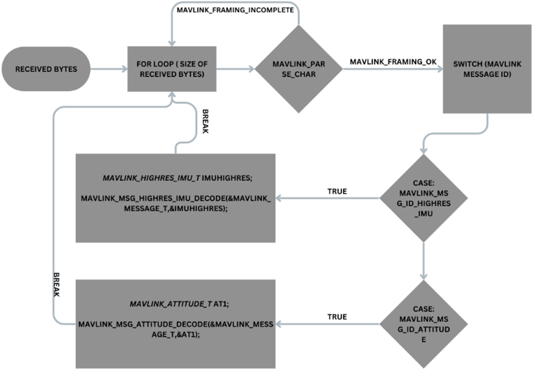
MAVLink message decoding flowchart.
Sending and Reading Buffer
A packet of information is ready to be delivered serially using the boost library serial_port, in which the async_write_some() function is used to write data to a target device asynchronously. The entire message is encoded via the MAVLink encode function and converted into a mavlink_message_t to be then sent to Pixhawk, which has the ability in its firmware to understand MAVLink messages; therefore, there is no need for a loop to store information in an array.
Again, the boost library serial_port is needed, as it has a function called async_read_some(). This reads the bytes received from the serial port and returns an array of information, which will then be decoded by MAVLink. To avoid noise or delays, the binding of the decoding buffer and the reading buffer functions is required.
A MAVLink bridge has been developed between the control station and Pixhawk; however, in the case of telemetry, it is necessary to counteract any delay that may occur due to a lower transfer rate and loss of communication. This can be achieved by switching from the primary link to the secondary link, and MAVLink also facilitates the use of the high-latency data transfer mode of MAVLink 2.0.
Ground Autopilot Test Capability (Test Scenario)
The dynamics can be modelled using the following system state variables: longitude (px), latitude (py) and altitude (pz) for position; u, v and w for velocity; roll (γ), pitch (θ) and yaw (ψ) for attitude; ωx, ωy and ωz for angular rate; ax, ay and az for acceleration; Va, Vg for air speed and ground speed; α for the attack angle and β for the slide-slip angle, respectively. The control inputs of the aircraft include the left and right ailerons (δa-1, -2), which are responsible for lateral motion(γ), the elevators (δe), which provide longitudinal motion(θ), the rudder (δr), which provides directional control (ψ) and the throttle (δt) for thrust control.
A sample autopilot mode, such as heading control, can be integrated within the application. Prior to heading control, stabilisation of the yaw rate (R) at approximately zero radians per second is required by actuating the rudder to prevent an oscillating behaviour in the aircraft, commonly known among pilots as “Dutch roll”, when using the ailerons to achieve the desired heading position. A basic PID algorithm and testing can only be performed when the aircraft is provided with a small perturbation in bank angle (γ). For the PID variables, the desired value is zero, and the current value is the yaw rate with a rudder limiter of 10% to −10%. This percentage will be converted to a Pulse Width Modulation (PWM) signal. This signal is then sent to Pixhawk ports via MAVLink.
After eliminating unnecessary oscillations in the lateral axis with a yaw damper, a cascade PID controller is deployed to achieve the heading control autopilot. Figure 6 illustrates a cascading controller:
FIGURE 6

Sample heading autopilot algorithm.
The above controller is designed to control the heading guidance on the ground while the aircraft is taxiing on the ground. This ensures that the aircraft responds to commands sent through the GCS using the MAVLink protocol in real-time environments.
Results and Discussion
Executable_bridge and AeroQt are both open-source applications that can be found under the JSBSim repository. They were designed separately for SITL and HITL simulations using Pixhawk sensors and actuators, and development is ongoing on GitHub, with the majority of programmers trying to integrate them with MAVROS to visualise simulations.
Qt Creator, which is free to use, appears to be the perfect tool for customising control panels according to requirements and for integrating MAVLink with JSBSim for HITL simulations. Executable_bridge originally could only write messages to Pixhawk, and it was interlinked with QGC to receive actual sensor and GPS data. Figure 7 shows the custom features added to the application for HITL simulations and the addition of indigenous autopilot modes.
FIGURE 7
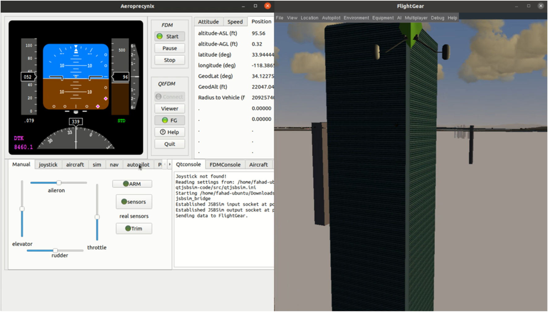
Addition of features to QTJSBSim for HITL.
All the results shown in SITL would be the same in HITL, but the actual actuator/servo status is required for verification that MAVLink communication is working and that the actuator response in JSBSim is aligning with the response of the real actuators mounted on Pixhawk. In Figure 8, a heading follower autopilot was implemented to observe and compare the FDM and real servo responses of the actuator aileron. This is because a direct servo signal varying from 1 to −1 cannot be sent through the JSBSim property node. A mapping function is required to match the two ranges, i.e., the servo signals to PWM, which range from 1000 to 2000. This ensures that the actuator mapping algorithm works well and that the real servo accurately follows the servo signal generated by the FDM. This is shown in Figure 9.
FIGURE 8
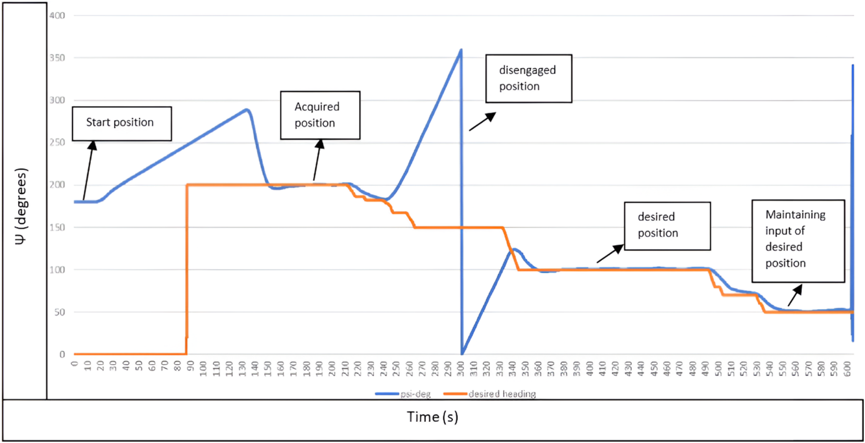
Heading autopilot response.
FIGURE 9
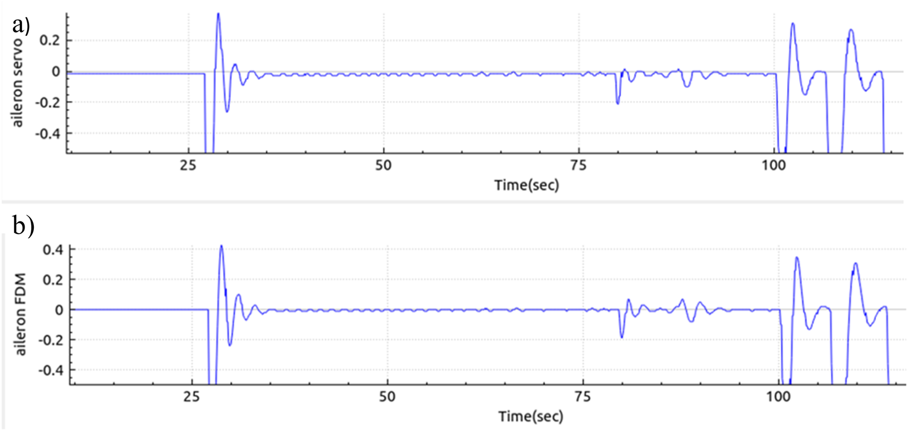
HITL aileron servo response; (a) Aileron servo response and (b) Input signal from FDM.
The heading control performance was evaluated using a single test run, with the results quantified to complement the descriptive plots. The Root Mean Square Error (RMSE) between the desired and actual heading was 2.51°, indicating a low average deviation. The maximum observed error was 2.88°, with a standard deviation of 0.54°, suggesting the controller maintained stable and consistent performance throughout the test (Table 2). Although only one test was conducted, these metrics support the visual evidence of convergence and control accuracy. Additional trials and statistical averaging are planned for future work to strengthen confidence in the controller’s generalizability.
TABLE 2
| Metric | Value (degrees) |
|---|---|
| RMSE | 2.51 |
| Max Error | 2.88 |
| Standard Deviation | 0.54 |
Analysis of errors in heading control performance.
Effect of Sensor Noise on Control Performance
A PID based control system can undergo significant performance related circumstances in simulations when sensor noise is introduced. AeroQT is equipped with numerous autopilot modes, but for the purpose of benchmarking control performance, heading control is taken into consideration. Figure 10 shows the aileron control response before noise induction:
FIGURE 10
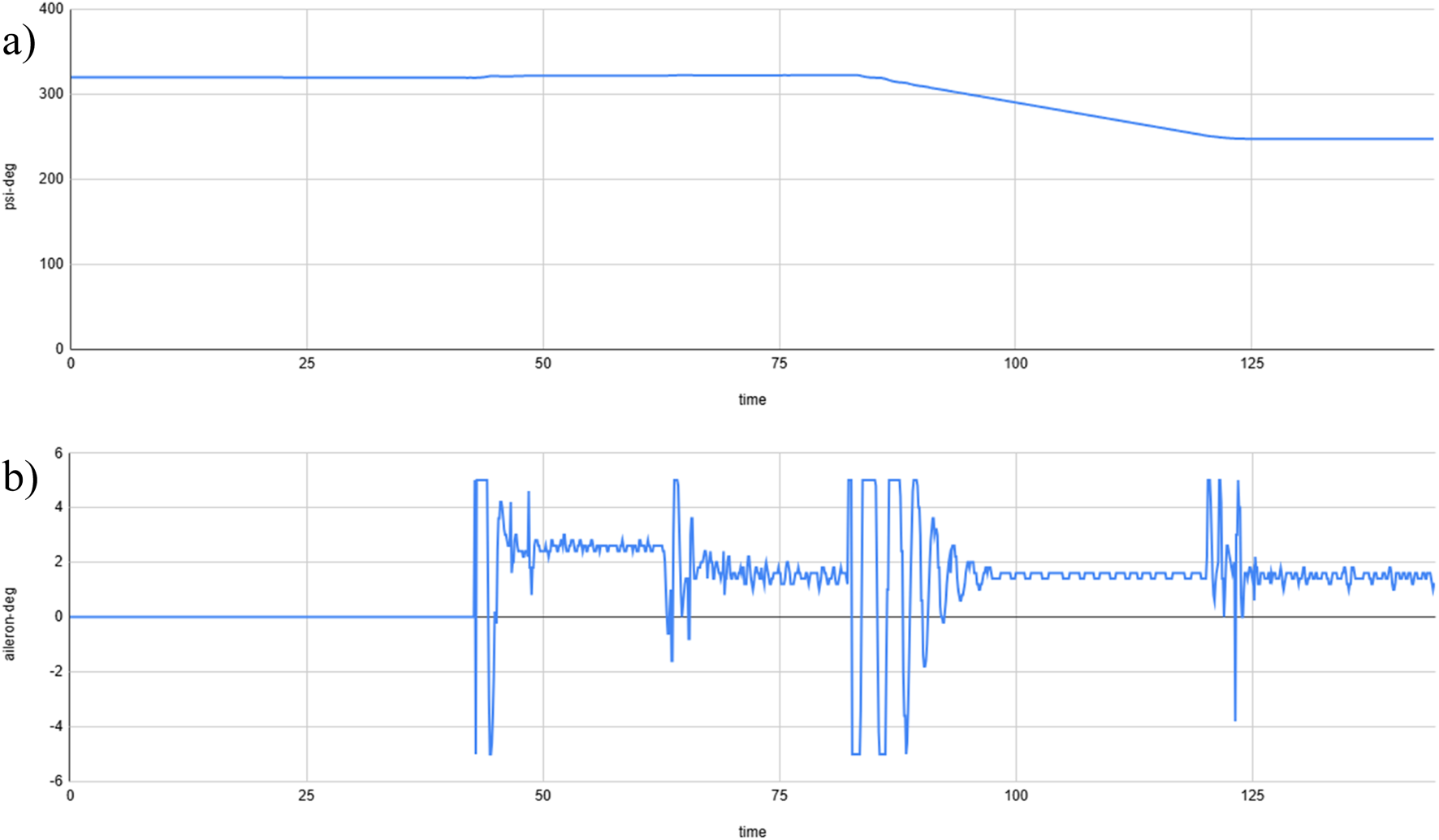
Control response of the aileron without Gaussian noise; (a) Pure heading without noise induction, and (b) Aileron control without noise.
Gaussian noise with a variation of 0.002% induced into a yaw sensor (magnetometer):
<sensor name=“new-sens/noisy-heading”>
<input>altitude/psi-deg</input>
<lag> 0 </lag>
<noise variation=“PERCENT” distribution= “GAUSSIAN”> 0.002 </noise>
</sensor>
Figure 11 shows aileron control response after noise induction:
FIGURE 11

Control response of the Aileron after applying 0.002% Gaussian noise; (a) Noise induction in the heading output response and (b) Aileron control variation due to noise.
Figure 11 shows the control response of the aileron input after a 0.002% noise induction. The PID heading control is able to correct the aircraft heading without further need for tuning in case of sensor noise, but causes a continuous higher degree of actuation, which can result in more power consumption. Further tuning or the application of a Kalman filter could address this continuous actuation, but this is beyond the scope of this research.
Data Quantification and Comparison With QGroundControl (QGC)
Mission planners such as QGC and APM have been using MAVLink in an optimised way. Meanwhile, numerous efforts have been made to deliver a control device for Pixhawk-based aircraft with much less data loss and rapid data transmission. MAVLink testing must be evaluated with USB serial (SITL) and via telemetry, comparing the transfer rate with that of mission planners. USB serial in MAVLink usually operates at a baud rate (signal units per second) of 921,600, while radio telemetry can operate at a baud rate in the range of 9,600 to 115,200.
Taking the PX4 IMU sensors into account for observation, we can observe that the PX4 has built-in altitude estimators that take IMU sensor data as input and provide aircraft altitude as output. The serial USB data rate is presented in Figure 12a, and the data rate using telemetry is shown in Figure 12b.
FIGURE 12
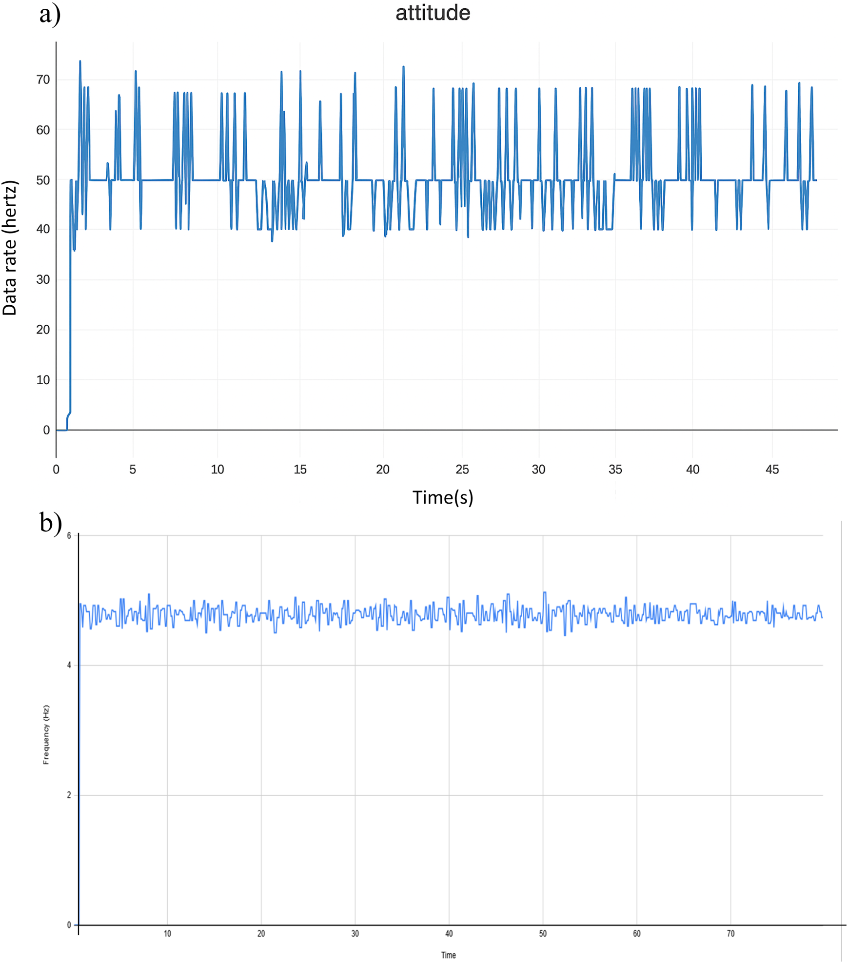
Data rates from the AeroQT application: (a) Using USB serial communication and (b) Using telemetry communication.
QGC is a well-established mission planner for Pixhawk-based vehicles and can be used as a means of comparison with our control station. Figure 12a shows that the AeroQT application can translate MAVLink messages at the same constant rate of 50 Hz as QGC via USB serial, as demonstrated by the altitude message incoming from Pixhawk.
When operating on telemetry at a baud rate of 57,600, the data rate is much lower than for serial port communication, but remains constant and stable at 4.25 Hz over a varying range of distances between the telemetry and flight controller, as shown in Figure 12B. Comparing with QGC with same baud rate, the data rate is still half of the rate at which QGC is operating at, can be seen in the Figure 13.
FIGURE 13
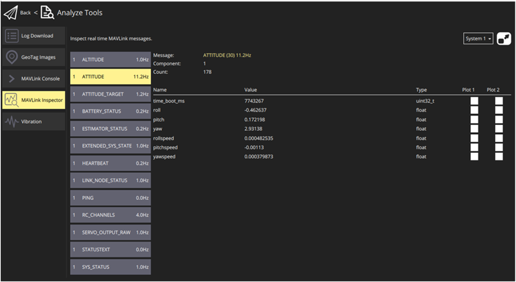
Data rate from QGC via telemetry.
Although both QGroundControl and AeroQT receive MAVLink messages from the same telemetry stream, a notable frequency disparity was observed: 11.5 Hz in QGC vs. 6.5 Hz in AeroQT. This difference is likely due to protocol handling and GUI update rates. QGC aggressively polls and visualises incoming MAVLink messages with optimised multi-threaded handling, whereas AeroQT, being a lighter-weight interface, limits update frequency to reduce CPU usage and conserve bandwidth. Additionally, message throttling or internal MAVLink parsing intervals (e.g., event-driven updates in AeroQT) may further reduce the apparent message rate.
The underlying cause of these frequency differences can be explained by estimating the one-way latency from PX4 to AeroQT and the packet drops that occur when using a radio telemetry connection. The MAVLink TIMESYNC message has been utilised for latency estimation and performs a simplified version of the Network Time Protocol (NTP). This allows the systems to:
Estimate Round-Trip Latency (RTT)
Estimate the clock offset between systems
Optionally synchronise clocks
Figure 14 shows the effects of latency, packet loss and frequency when using telemetry. When telemetry is connected at a baud rate of 57,600, the latency appears to fluctuate around 400 ms, which poses challenges for time-sensitive control loops. This high latency is likely attributable to network stack buffering, simulator scheduling delays, or MAVLink message queuing. Such delays can degrade the performance of HITL testing and limit responsiveness in offboard modes. To mitigate the observed latency of 400 ms, future implementations may benefit from a lower-bandwidth MAVLink profile, real-time scheduling of the simulator process, or direct serial/USB telemetry instead of Wi-Fi-based UDP.
FIGURE 14
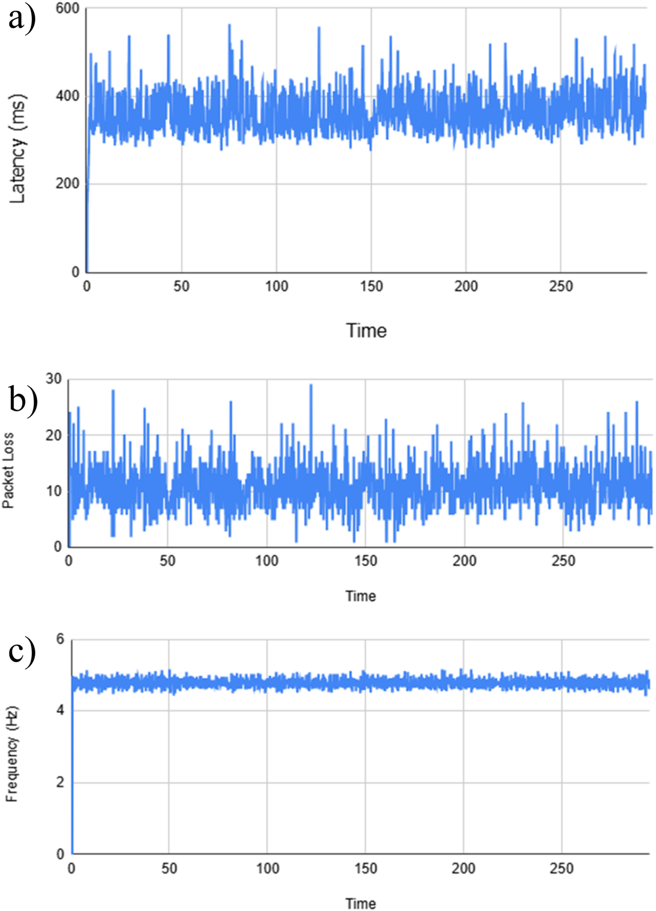
(a) Latency, (b) Packet Loss and (c) Frequency plot while connected via radio telemetry.
In our HITL loop, the measured telemetry delay is approximately T = 0.4 s. A pure time delay contributes to a frequency-dependent phase lag. The phase lag delay (φ_delay) equation is used to calculate phase lag using Equation 1.
At the loop crossover frequency (ω_c), this lag subtracts directly from the phase margin using Equation 2, which provides a new phase margin, PM_new.where PM_0 is the margin without delay. To guarantee the required phase margin (PM_req, typically 30°–45°), the allowable crossover frequency must satisfy the bandwidth limit. Therefore, logical equations are placed, i.e., Equations 3, 4:
(with PM_req expressed in radians).
For T = 0.4 s, the required margins are found to be:
With a required margin of 45° (≈0.785 rad), f_c ≤ 0.31 Hz (ω_c ≈ 1.96 rad/s).
With a required margin of 30° (≈0.524 rad), f_c ≤ 0.21 Hz (ω_c ≈ 1.32 rad/s).
Thus, a 400 ms delay limits the closed-loop bandwidth to approximately 0.2–0.3 Hz if stability margins are to be preserved. At 1 Hz, the delay alone would add −144° of lag, enough to destabilise the majority of the loops. In addition to this, inner-loop altitude and rate control must remain onboard the Pixhawk (50–400 Hz), while only slower outer loops (e.g., position, path, or energy management) can be closed through the delayed HITL channel.
Conclusion
In the field of aircraft development and testing via SITL and HITL simulations, JSBSim enables the rapid prototyping and iteration of aircraft designs. Engineers can quickly modify aircraft parameters within the simulation environment and evaluate their impact on performance, stability, and control without having to make physical changes to an aircraft. The need arises for a test bed application that can cater for both types of simulation. Therefore, the outcome of this research focused mainly on a universal platform to serve this purpose, with indigenous MAVLink integration enabling actual flight tests to be conducted during ground taxi phases, as demonstrated in this study.
It is worth mentioning that output frequency testing is bound to either USB or telemetry and demonstrated a similar frequency of 50 Hz to QGC; however, in the case of telemetry, it was 6.5 Hz, half of the actual frequency of 11.5 Hz.
AeroQT provides a lightweight, standalone platform that integrates MAVLink parsing and flight dynamics modelling into a single runtime, significantly reducing the setup complexity of HITL testing. Its Qt-based interface offers intuitive visualisation through a Primary Flight Display, navigation data, and autopilot tabs, enabling engineers to focus on control algorithm design and autopilot evaluation without requiring expertise in C++ or MAVLink internals. These strengths distinguish AeroQT from traditional ground control software, which is typically more complex and mission-orientated. Nevertheless, some limitations remain: the current version is primarily suited to single-aircraft evaluation with JSBSim; it does not yet support advanced mission planning, multi-UAV scalability, or external simulators; and the observed telemetry delay (∼400 ms) restricts the real-time controller bandwidth, which slows the outer loops. Future work will address these gaps by improving portability, expanding simulator and autopilot compatibility, adding richer visualisation and logging features, and developing scripting interfaces to enable automation and multi-vehicle experimentation.
Nevertheless, this article is also a guide for implementing MAVLink communication in C++ with Pixhawk and other supported FCU protocols. By following the guidelines outlined in this study, readers can confidently develop MAVLink-based communication systems for their UAVs, leveraging the power and flexibility of C++.
Statements
Data availability statement
The raw data supporting the conclusions of this article will be made available by the authors, without undue reservation.
Author contributions
FA designed the study and draughted the manuscript. FA and AL conducted the experiments and analysed the data. AL supervised the project and revised the manuscript. All authors contributed to the article and approved the submitted version.
Funding
The author(s) declare that financial support was received for the research and/or publication of this article. This research was partially funded by IGNITE NIGRI for the provision of flight controllers and fixed-wing UAVs.
Acknowledgments
We thank the Faculty of Mechatronics at PAFKIET for their assistance and for providing well-equipped laboratories in which to conduct this study.
Conflict of interest
The authors declare that the research was conducted in the absence of any commercial or financial relationships that could be construed as a potential conflict of interest.
Generative AI statement
The author(s) declare that no Generative AI was used in the creation of this manuscript.
Any alternative text (alt text) provided alongside figures in this article has been generated by Frontiers with the support of artificial intelligence and reasonable efforts have been made to ensure accuracy, including review by the authors wherever possible. If you identify any issues, please contact us.
Abbreviations
HITL, Hardware-in-the-loop; SITL, Software-in-the-loop; GUI, Graphical User Interface; FDM, Flight Dynamics Model; UAV, Unmanned Aerial Vehicle; ROS, Robot Operating System; UDP, Universal Datagram Protocol; GCS, Ground Control Station; IMU, Inertial Measurement Unit; FCU, Flight Control Unit; QGC, Q-Ground Control Station; NTP, Network Time Protocol; RTT, Round-Trip Latency.
References
1.
Loya A Haider A Ghaffor AA Siddique A . Real Time Data Communication with FlightGear Using Simulink over a UDP Protocol. open Sci index (2021) 16:1.
2.
Loya A . Development of the Flight Dynamic Model (FDM) Using Computational Fluid Dynamics (CFD) Simulations for an Unknown Aircraft. In: Computational Fluid Dynamics Simulations: Intechopen (2020).
3.
Zhang Z Yang W Shi Z Zhong Y . Hardware-In-The-Loop Simulation Platform for Unmanned Aerial Vehicle Swarm System: Architecture and Application. In: 2020 39th Chinese Control Conference (CCC). IEEE (2020). p. 58–64.
4.
Luo Z Xiang X Zhang Q . Autopilot System of Remotely Operated Vehicle Based on Ardupilot. In: Intelligent Robotics and Applications: 12Th International Conference, ICIRA 2019, Shenyang, China, August 8–11, 2019, Proceedings, Part III 12, 2019. Springer. p. 206–17.
5.
Jiang Z Patil T . A Distributed Hardware-in-the-Loop Simulation Testbed for Swarms of Small Autonomous Vehicles. In: AIAA AVIATION 2022 Forum (2022). p. 4057.
6.
Hangal SA Tak B Arya H . Distributed Hardware-in-Loop Simulations for Multiple Autonomous Aerial Vehicles. In: AIAA Modeling and Simulation Technologies Conference (2015). p. 0151.
7.
Elgohary AA Ashry AM Kaoud AM Gomaa MM Darwish MH Taha HE . Hardware-In-The-Loop Simulation of UAV Altitude Hold Autopilot. In: AIAA SCITECH 2022 Forum (2022). p. 1520.
8.
Prochazka F Krüger S Stomberg G Bauer M . Development of a Hardware-in-the-Loop Demonstrator for the Validation of Fault-Tolerant Control Methods for a Hybrid UAV. CEAS Aeronaut J (2021) 12(3):549–58.
9.
Parker MZ . Automated Landing of a Fixed-Wing Unmanned Aircraft onto a Moving Platform. (2023).
10.
Domin K Marin E Symeonidis I . Security Analysis of the Drone Communication Protocol: Fuzzing the MAVLink Protocol (2016).
11.
JSBSim. JSBSim Reference Manual (2025). Available online at: https://jsbsim.sourceforge.net/JSBSimReferenceManual.pdf.
Summary
Keywords
MAVLink C++ implementation, HITL/SITL, Qt application, virtual flight control, autopilot development
Citation
Aziz F and Loya A (2025) Multi-Mode MAVLink Test Bench AeroQT for Aircraft Simulation and Real-Flight Validation. Aerosp. Res. Commun. 3:14524. doi: 10.3389/arc.2025.14524
Received
22 February 2025
Revised
22 September 2025
Accepted
15 October 2025
Published
20 November 2025
Volume
3 - 2025
Updates
Copyright
© 2025 Aziz and Loya.
This is an open-access article distributed under the terms of the Creative Commons Attribution License (CC BY). The use, distribution or reproduction in other forums is permitted, provided the original author(s) and the copyright owner(s) are credited and that the original publication in this journal is cited, in accordance with accepted academic practice. No use, distribution or reproduction is permitted which does not comply with these terms.
*Correspondence: Adil Loya, loya_adil@yahoo.com
Disclaimer
All claims expressed in this article are solely those of the authors and do not necessarily represent those of their affiliated organizations, or those of the publisher, the editors and the reviewers. Any product that may be evaluated in this article or claim that may be made by its manufacturer is not guaranteed or endorsed by the publisher.