Abstract
Traditional aerodynamic design faces significant limitations in modeling and computational efficiency during conceptual design stage. A phased collaborative aerodynamic design strategy for eVTOL aircraft was established, by combining the OpenVSP platform for rapid parametric modeling and evaluation, a Kriging surrogate framework with an improved differential evolution algorithm for optimization, and the SUAVE platform for propeller reverse design. In the wing-body (WB) optimization phase, 23 configuration parameters such as the wing shape and location were adjusted. The aerodynamic evaluation was conducted using the Vortex Lattice Method (VLM) in OpenVSP, resulting in a 9.3% increase in the lift-to-drag ratio (L/D). During the wing-body-propeller (WBP) coupling optimization phase, the Actuator Disk Theory (ADT) was incorporated into WB model to quantify the slipstream effects. After optimizing the key geometric parameters such as disk diameter and location, the comprehensive propulsion efficiency and lift-to-drag ratio (η·/L/D) was increased by 14%. Relative performance parameters were then transferred to SUAVE to reconstruct the propeller based on the Betz-BEM theory. The RANS high-fidelity verification of the optimized WBP model shows high consistency in the trends of lift coefficient Cl and L/D calculated by VLM, with the propeller thrust error 5.2%, and the Cl error 9.7%, which confirms the engineering reliability and efficiency of the proposed strategy.
Introduction
With urbanization accelerating, traditional ground transportation systems face severe traffic congestion, with peak-hour vehicle speeds below 15 km/h in megacities [1]. The Urban Air Mobility (UAM) systems have emerged as a breakthrough solution, with Electric Vertical Take-Off and Landing (eVTOL) aircraft becoming a pivotal technology due to its vertical takeoff/landing capability, high cruising efficiency, and environmental benefits [2–5].
Aircraft modeling is the primary link in aircraft design. Although traditional CAD tools (such as CATIA) are widely used, their limitations become prominent in the conceptual design stage. Ronzheimer et al. [6] developed a design table-driven parametric framework using CATIA V5, enabling high-precision modeling and CFD-compatible optimization of propeller blades and blended-wing-body (BWB) configurations. Bhise et al. [7] proposed a parametric CATIA modeling approach for wings of the short range and narrow body aircraft, integrating Ansys Fluent aerodynamic analysis with Python scripting to generate NURBS curves. However, these methodologies rely on manual hierarchical feature tree construction, resulting in disconnected parameterization logic from engineering semantics. Geometric inconsistencies frequently arise during parameter adjustments, and iterative efficiency remains inadequate for large-scale design exploration. Regarding deformation-based methods, Lyu et al. [8] employed Free-Form Deformation (FFD) for aerodynamic optimization of BWB configurations, quantifying design variable impacts on performance metrics. Li et al. [9] combined FFD with a discrete adjoint method using Reynolds-Averaged Navier-Stokes (RANS) simulations, achieving a 5.7% reduction in total drag for supersonic airliner configurations. Nevertheless, FFD methods suffer from the “curse of dimensionality” due to excessive control points, limiting their applicability to localized geometry adjustments. Their dependence on initial baseline models prevents autonomous topology generation, thereby constraining innovative design possibilities.
As the core power component of the eVTOL aircraft, the aerodynamic characteristic analysis of the propeller is the basis for design optimization. For performance evaluation of an isolated propeller, high-fidelity Computational Fluid Dynamics (CFD) methods based on the RANS equations are widely utilized, such as the Multiple Reference Frame (MRF)-RANS and Unsteady RANS (URANS). These methods are capable of accurately capturing three-dimensional flow and viscous effects. For instance, Bryant et al. [10] utilized the RANS method to calculate the thrust of a small-scale propeller, but it took 14–15 h (160 threads) under a single working condition. Liu et al. [11] compared the accuracy differences between MRF-RANS and the Blade Element Momentum Theory (BEMT), and found that while RANS exhibited lower errors (with propulsive efficiency errors below 10%), it required 900 CPU hours under a single working condition. However, in the actual flight conditions of eVTOL aircraft, the strong coupling effects between the propeller and the wing significantly influence the overall aerodynamic performance. Consequently, analyzing only the isolated propeller is insufficient to meet design requirements.
For the wing-propeller aerodynamic interaction analysis, it is also necessary to balance the efficiency and accuracy of high-fidelity methods. Sinnige et al. [12] employed the Unsteady Reynolds-Averaged Navier-Stokes (URANS) approach to analyze the dynamic stall characteristics of the NASA LA-8 tilt-configuration aircraft during cruise and transition flight states. The error compared with experimental data was less than 8%. Li Peng et al. [13] explored the influence of tilting rotors on the wing and fuselage drag in hovering and cruising states through the RANS-based overset grid technique. Xu et al. [14] analyzed the influence of the lower slipstream of the upper propeller of the coaxial reverse-rotating propeller configuration eVTOL aircraft on the pull performance of the lower propeller based on MRF-RANS, and quantified the pull performance loss (about 33%). Although the RANS method can analyze the nonlinear influence of slipstream on the pressure distribution over the wing [15–18], its single-condition calculation cost is as high as several hundred CPU hours, which seriously restricts the optimization efficiency.
In the field of aerodynamic shape optimization, although the research based on surrogate models or discrete adjoint gradient methods has achieved the coupling optimization of propellers and wings [19–21], aerodynamic analyses all rely on high-fidelity calculation methods such as RASN. For example, Yildirim [22] utilized a high-fidelity computational method based on the OpenMDAO/MPhys framework for the optimization of an eVTOL wing-propeller aerodynamic interaction, which achieved an 18.3% reduction in power under all constraint conditions. Chauhan [23] conducted aerodynamic simulations of a distributed electric propulsion eVTOL using the ADT-RANS method, which combines the Actuator Disk Theory (ADT) with Reynolds-Averaged Navier-Stokes (RANS) equations. A gradient-based optimization algorithm was then employed to minimize cruise drag. However, the design variables were limited to the propeller’s rotation direction, the wing’s twist, and airfoil shape. Pedreiro [24] referred to the Embraer EMB-120 and optimized the twist distribution and airfoil shape of the wing behind the propeller using RANS-ADT with six design variables. Eventually, the drag was reduced by three counts under cruising conditions. Although the high-fidelity method based on the RANS equations can accurately simulate the viscous interference effects between the propeller slipstream and the wing, the significantly high computational cost hinders multivariable optimization of eVTOL. To reduce complexity, while there are existing studies have combined low-fidelity vortex lattice methods or BEMT with surrogate models for aerodynamic shape optimization of eVTOL, the optimizations of the wing and propeller are performed separately [25, 26].
To balance the contradiction between efficiency and accuracy in aircraft design and aerodynamic optimization, the open-source tools based on NASA’s OpenVSP offer a new approach. Its parametric component library and script-driven modeling framework enable the construction of eVTOL models within minutes through adjusting predefined geometric variables, eliminating the need for manual feature reconstruction at each design iteration. Its Unsteady Vortex Lattice Method (UVLM) enables rapid performance evaluation of isolated propellers. For instance, Sun Zongyan et al. [27] adopted UVLM to analyze the distributed propulsion configuration eVTOL, achieving lift coefficient Cl and drag coefficient Cd errors less than 5% and 4.6% within the linear region. Yu et al. [28] utilized OpenVSP’s UVLM and the steady RANS method based on the k-ω SST turbulence model in Simcenter STAR-CCM+ software to conduct performance analyses on a single three-bladed propeller. The differences in thrust and torque calculations between the two methods were less than 10% and 5%. Sheridan et al. [29] calculated propeller thrust using both OpenVSP’ss UVLM and OVERFLOW’s URANS. The differences in thrust and torque calculations between the two methods were less than 10% and 2%. The UVLM method took only a few minutes under a single working condition. Wu et al. [30] developed the ADT-VLM (Actuator Disk Theory-Vortex Lattice Method) framework to enable efficient simulation of propeller-wing aerodynamic interactions. This approach achieves Cl and Cd deviations below 10% compared to RANS results. Yu et al. [28] validated ADT-VLM’s capability to capture three-bladed propeller slipstream characteristics, demonstrating Cl deviations below 6% relative to steady RANS simulations, while computational efficiency achieved less than 1 min under a single working condition.
However, existing studies have not yet fully utilized OpenVSP’s parametric modeling capabilities. There remains an urgent need to establish an integrated optimization framework combining ADT-VLM with surrogate modeling. Unlike conventional decoupled optimization strategies, the ADT-VLM methodology eliminates velocity field discrepancies between slipstream conditions and design points through coupled analysis. When integrated with Kriging surrogate models, this approach significantly reduces computational costs to achieve global propeller-wing coupling optimization.
Numerical Simulation Methods and Aerodynamic Validation
Vortex Lattice Method Theory
The Vortex Lattice Method (VLM) is based on the potential flow theory, which discretizes the aircraft surface into vortex lattices to simulate the surrounding flow field. It is suitable for rapid aerodynamic performance evaluation under small angle of attack and low speed conditions, offering significant efficiency advantages during conceptual design phases. OpenVSP implements VLM calculations through VSPAERO tool, which can output key parameters such as Cl and Cd.
Based on the lifting surface theory [31], the classical VLM simplifies the wing into discrete thin lifting surfaces with horseshoe vortices deployed. Each panel contains a horseshoe vortex composed of bound vortex lines and free vortex lines, with circulation strength Γ. A control point P is established at the midpoint of the 3/4 chord line of each panel (as shown in Figure 1a). The induced velocity from vortex segment ab at control point P is calculated using the Biot-Savart law [32], expressed as Equation 1:
FIGURE 1
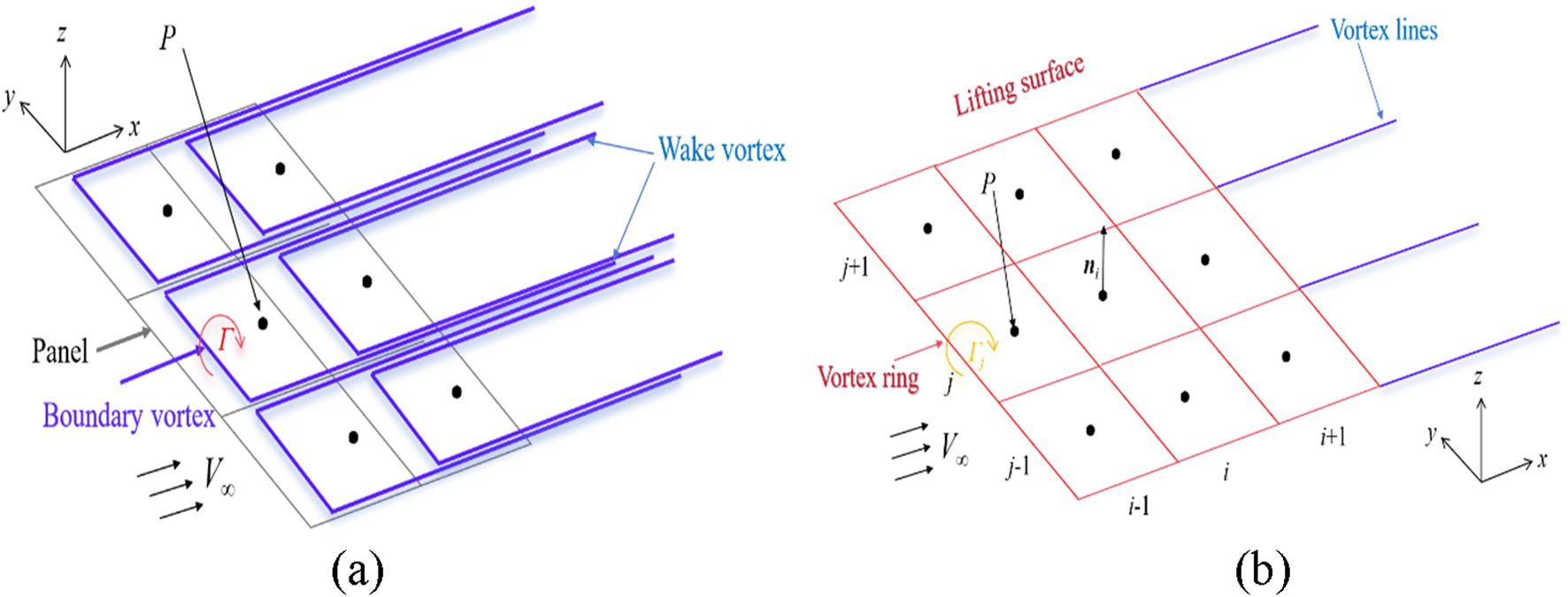
Diagram of VLM principle. (a) Basic VLM; (b) open VSP VLM.
In contrast, OpenVSP employs an improved VLM that replaces horseshoe vortices with a vortex ring model. Vortex rings are placed at panel centers, with their geometric center point P acting as the singularity (similar to the control point in horseshoe vortices). Wake vortices are represented by trailing vortex lines from trailing-edge wake points (Figure 1b). The Prandtl-Glauert compressibility correction factor is introduced to account for compressibility effects [33]. Induced velocities are computed using the Biot-Savart law, expressed as Equation 2:where represents the strength of the vortex ring, and K is the factor considering the influence of compressibility on the calculation: if , then K = 2; otherwise, K = 1, is defined by Equation 3
By incorporating these velocities into the Neumann boundary condition [34], the vortex ring strengths are solved iteratively. Aerodynamic loads are subsequently calculated using the Kutta-Joukowski theorem [35]. Some researchers contend that VLM implementation in VSPAERO constitutes an advanced lifting-surface method rather than a technically pure VLM [36].
Actuator Disk Theory
The Rankine-Froude momentum theory was extended to the actuator disk theory to estimate propeller thrust through simplified flow modeling [37]. VSPAERO implements an improved formulation combining Conway’s elliptical actuator disk model [38] and Johnson’s tangential velocity model [39], which enables the calculation of axial velocity, radial velocity, and the pressure jump across the disk surface.
According to [38], the axial velocity induced by a propeller of radius R at a point (r,z), where r is the radial coordinate ranging from 0 to R and z is the axial coordinate with the origin (0,0) (corresponding to the disk center) is described by Equations 4, 5:
The radial velocity is given by Equation 6, is defined by Equation 7, and the pressure jump across the disk surface is given by Equation 8.
In Equations 4–8, the remaining terms are defined as follows: the axial velocity at the center plane of the disk is given by Equation 9, and the induced velocity is given by Equation 10,where T is the propeller thrust (obtained by inputting the thrust coefficient CT), and A is the projected area of the propeller disk. Finally, the parameter α (not to be confused with the angle of attack) is defined by Equation 11.
The tangential velocity is modeled considering the power losses due to the viscous drag of the blade. Consequently, Johnson’s equation relies on the blade’s lift-to-drag ratio (Cl/Cd). However, VSPAERO, based on the assumptions outlined in literature [39], circumvents the need to provide blade aerodynamic data. The tangential velocity is given by Equation 12, where is defined by Equation 13.
The Cl/Cd is modeled by combining the blade hover thrust coefficient () and the hover power coefficient (), leading to Equations 14, 15.
Equation 14 defines the average Cl assuming the entire blade is in operation, with σ representing the blade solidity. The first term in Equation 15 is the profile drag power coefficient for a blade with a constant chord length and a constant drag coefficient, and the second term represents the hover induced power loss, which is corrected by an empirical factor κ [39]. According to [39], when considering a linear inflow distribution, κ takes a value of approximately 1.17, which is also the value adopted in the VSPAERO code.
If input parameters CT, CP and RPM are provided, and can be calculated. Subsequently, the Cd/Cl term in Equation 12 can be estimated through simple Equation recombination, and then the tangential velocity can be calculated.
Grid Convergence Analysis
The computing resource in this work is the Intel Xeon E5-2698v3 processor, with a main frequency of 2.30 GHz, 16 cores and 32 threads. The method verification and optimization of OpenVSP based on the VLM, and the high-precision verification of RANS both use 20 threads.
The convergence of the grid is analyzed before the verification of VLM method. Based on OpenVSP’s VLM grid control logic, it employs an X-Z planar symmetric modeling method for wings, and the wing surface grid is controlled by chordwise nodes Num_W and spanwise nodes Num_U. The grid quantities in the chord direction and span direction are (Num_W-1)/2 and Num_U-1 respectively. To ensure mathematical closure of grid topology, OpenVSP requires Num_W = 4n+1 for wings and Num_W = 8n+1 for propellers (n is a positive integer). Additionally, grid refinement can be applied at specific locations such as the wingtip, wingroot, leading edge, or trailing edge. When the value is between 0 and 1, the grid will be refined, and the smaller the value, the higher the grid refinement level. When the grid refinement value is set to 1, it indicates no grid refinement will be performed.
This section selects the classic symmetric airfoil NACA 0015 as a case study [40]. The computational model adopts a rectangular wing configuration with a chord length c = 1.7 feet (0.518 m), a semi-span length b/2 = 5.59 feet (1.704 m), and an aspect ratio AR = 6.45. The wingtip features a rounded transition design to simulate the geometric characteristics of an actual wind tunnel model (Figure 2), effectively eliminating tip effects caused by sharp edges. The numerical calculations strictly adhere to the experimental conditions: a freestream Mach number Ma = 0.13 ( m/s), Reynolds number Re = 1.5 × 10⁶, and air density ρ = 1.225 kg/m3.
FIGURE 2
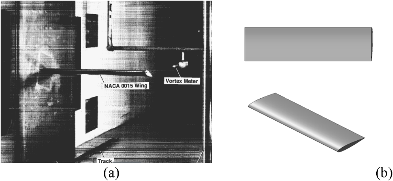
NACA 0015 wing model. (a) Wind tunnel test model; (b) open VSP model.
The study of grid convergence mainly investigates the influences of three grid-related variables: total grid count, spanwise-to-chordwise grid ratio, and local grid refinement. For the spanwise to chordwise grid ratio, two configurations are analyzed: 2:1 and 1:1. Both ratios cover the refined grid division (the wing leading edge/tip/root refinement factor is 0.25, the trailing edge refinement factor is 1) and unrefined grid division (refinement factors uniformly are 1). A total of 26 grid configurations are generated, with grid counts ranging from 96 to 13,068. Typical grid distributions for refined and unrefined cases are illustrated in Figure 3. By comparing the convergence curves of the Cl and Cd for different grid parameters (as depicted in Figure 4), it was found that the 1:1 aspect ratio grid without refinement exhibited the optimal convergence characteristics. When the angle of attack is 10, the difference in Cl between the 6,144 grids and 13,616 grids cases was only 0.54%. For the 2:1 aspect ratio grid with refinement, a Cl fluctuation of 1.8% was observed at high grid refinements, indicating that overly refined grids near the leading edge might trigger numerical oscillations. Based on these findings, the unrefined grid with an aspect ratio of 1:1 and 97 spanwise cells × 65 chordwise cells (totaling 6,144 grid cells) is selected as the baseline grid configuration.
FIGURE 3
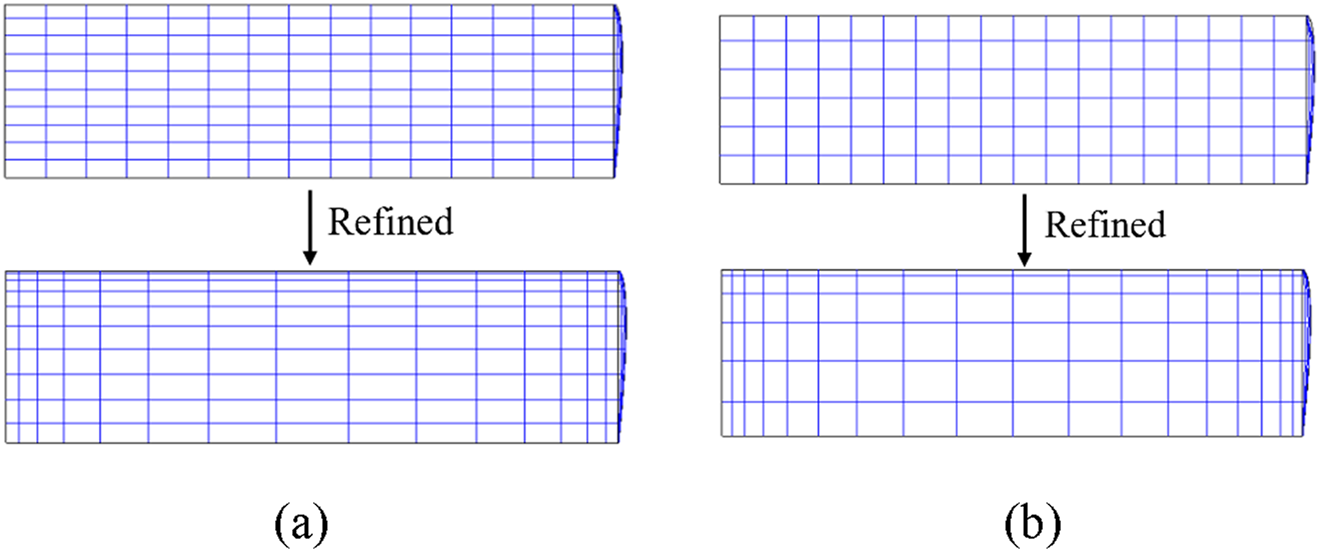
Schematic diagram of VLM grids with different densities. (a) Aspect ratio 2:1 (Grid count: 300); (b) aspect ratio 1:1 (Grid count: 216).
FIGURE 4
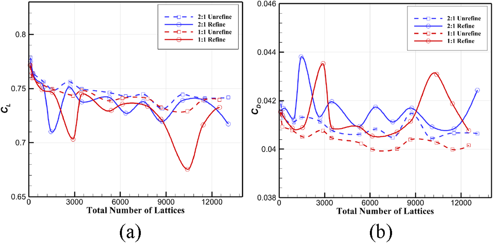
Grid convergence results of VLM aerodynamic analysis at 10° angle of attack. (a) Variation curve of CL; (b) variation curve of CD.
VLM Validation
Based on the above operating conditions and baseline grid configuration, the reliability of OpenVSP’s VLM is verified by calculating the Cl and Cd at different angles of attack in NACA 0015. Figure 5 shows the comparison of the calculation results of the VLM with experimental data in the 2°–14° angle of attack range. Within the 2°–12° angle of attack range, the computed Cl values exhibit a high degree of linear correlation with the experimental values (R2 = 0.897), with a root mean square error (RMSE) of 0.125. At low angles of attack (α = 2°), the relative error is 14.0% (computed value 0.154 and experimental value 0.179). As the angle of attack increases, the error gradually rises. In the stall transition region (α = 14°), the predicted Cl is 1.055, which is 15.3% lower than the experimental value of 1.245. However, the trend maintains a monotonic increase, consistent with the experimental data and does not exhibit a stall inflection point. The phase error in predicting the stall angle of attack is less than 1° compared to the experimental data.
FIGURE 5
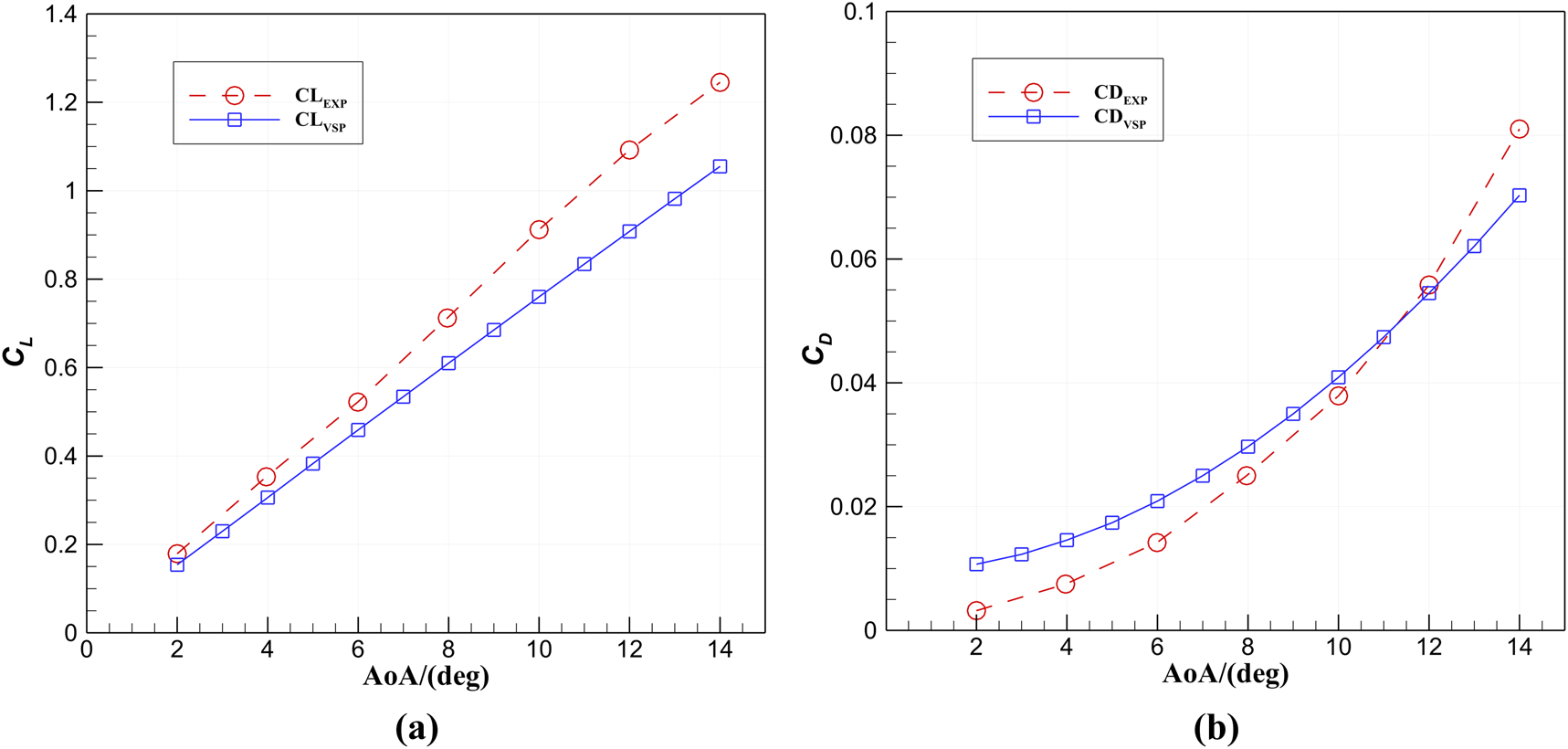
Comparison of VLM analysis results with experimental data. (a)CL at different angles of attack; (b)CD at different angles of attack.
ADT-VLM Validation
The PROWIM model [41], which has comprehensive wind tunnel test data, was selected for validation of the ADT-VLM. The configuration of the model is illustrated in Figure 6. The main body of the model features a straight wing with an aspect ratio of 5.33, the airfoil is NACA 642-A015 and a semi-span length is 0.64 m (b/2). The propulsion system consists of a four-bladed metal propeller with diameter D = 0.236 m, and its power unit is positioned 0.3 m along the wing’s mean aerodynamic chord. The nacelle’s rotational axis is coplanar with the turntable’s reference plane, with the maximum output power P = 5.5 kW. The flow conditions as follows: Re = 8 × 10⁵, Ma = 0.15, ρ = 1.225 kg/m3, and propeller advance ratio J = 0.85. The unrefined grid with an aspect ratio of 1:1 and 66 spanwise cells × 49 chordwise cells (totaling 3,120 grid cells) is selected as the baseline grid configuration. The propeller slipstream interference effect is evaluated using ADT-VLM. A comparison between the computational results and the experimental data is presented in Figure 7.
FIGURE 6
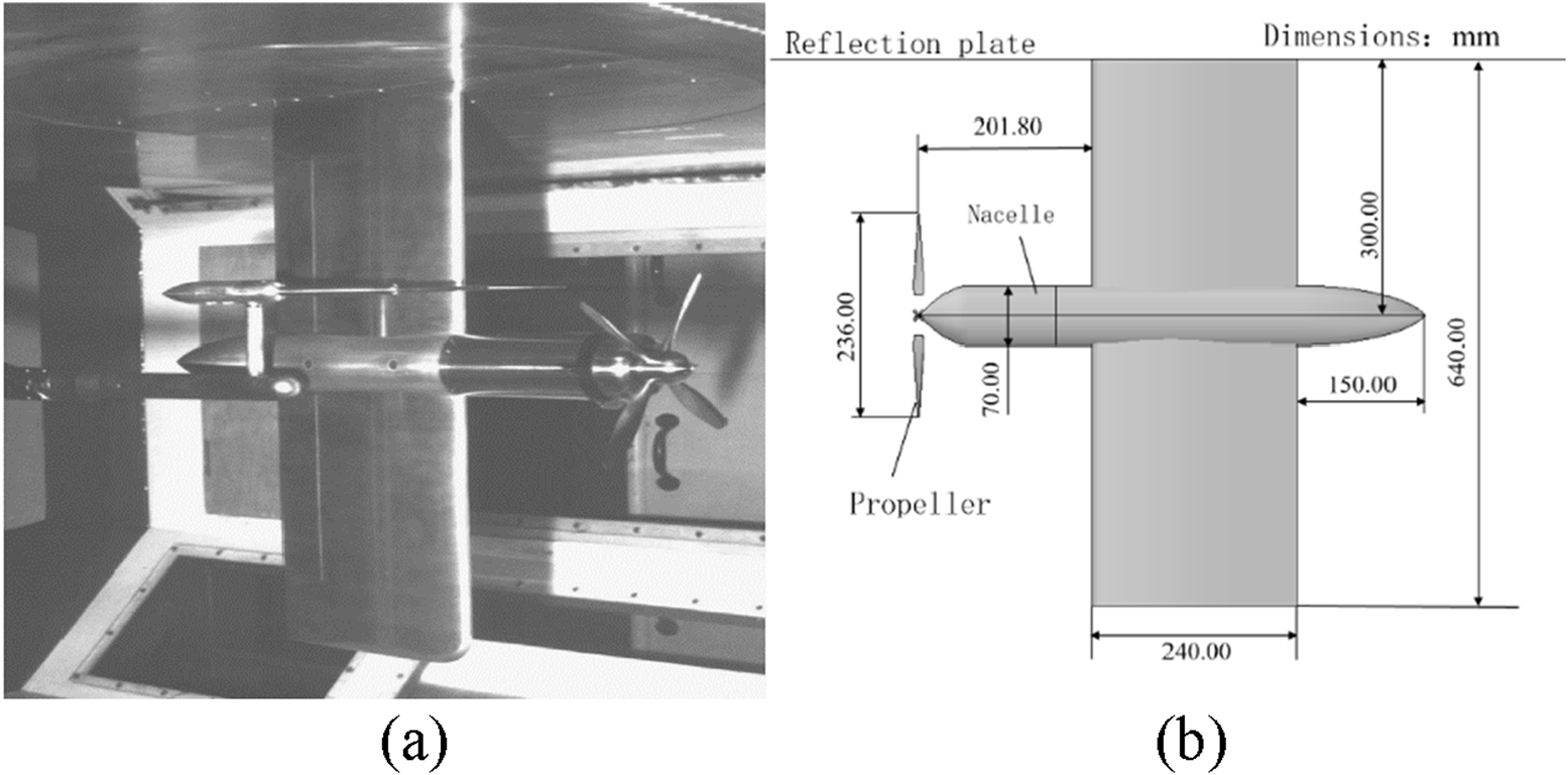
Diagram of PROWIM model. (a) Wind tunnel model; (b) top view and dimensions of model in open VSP (Unit: mm).
FIGURE 7
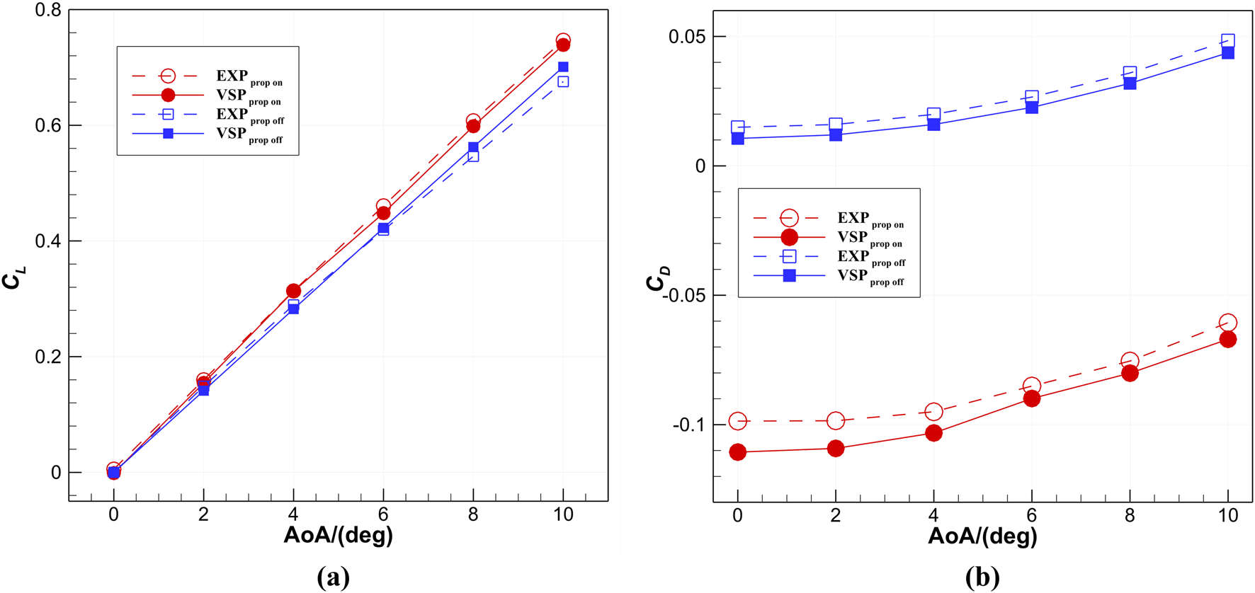
Comparison of ADT-VLM analysis results with experimental data. (a)CL at different angles of attack; (b)CD at different angles of attack.
Figure 7a shows that when α = 6°, the maximum Cl relative error between ADT-VLM and the test value is only 2.7%, which verifies the ability of this method to capture the slipstream enhancement effect. Notably, when α = 8°, the maximum relative error is merely 1.5%, indicating that it has high computational confidence at medium angle of attack. Figure 7b illustrates that when the propeller is on, the computed “Cd” appears negative because it includes the propeller’s thrust. By accounting for thrust correction and comparing the results with the experimental values, the validity of the method can still be verified. The results show that the maximum Cd error between ADT-VLM and the experimental value is less than 12.2%.
Comprehensive error analysis shows that VLM and ADT-VLM have good applicability in the concept design stage, and its single calculation time does not exceed 1 min, and its computing efficiency advantages are significant, laying the foundation for the subsequent optimization framework.
Rapid Parametric Modeling and Optimization Framework
OpenVSP-Based Parametric Modeling
In the process of parametric modeling and aerodynamic evaluation, the script-driven approach based on the OpenVSP platform achieves fully automated operations through predefined “.vspscript” files, as depicted in Figure 8. This script file embeds the geometric parameterization code and aerodynamic analysis code of each component of the aircraft. After Windows command line interface CMD calls the OpenVSP program, the script is executed to sequentially complete geometric modeling and aerodynamic analysis.
FIGURE 8
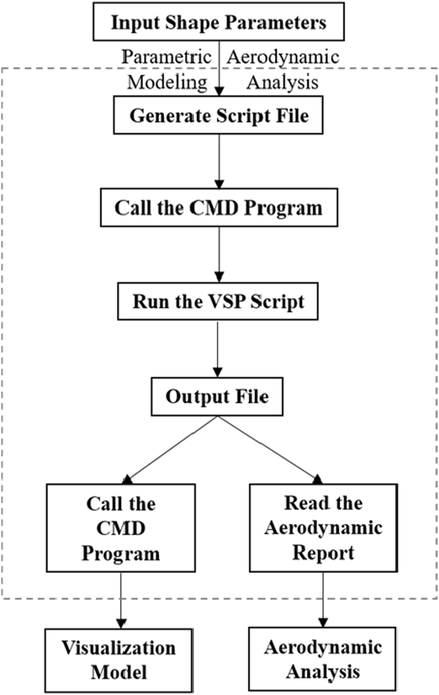
Execution process of parametric modeling and aerodynamic analysis using OpenVSP scripting.
The fuselage modeling is rapidly accomplished using the Fuselage component to create a streamlined shape, with side and front views shown in Figure 9a. The fuselage is divided into four segments, and each segment has an axial position controlled by XLocPercent parameters. The cross-sectional shape adopts an elliptical profile (the aspect ratio defined by Ellipse_Width and Ellipse_Height), and the end closure method is optimized by CapUMaxOption parameter.
FIGURE 9
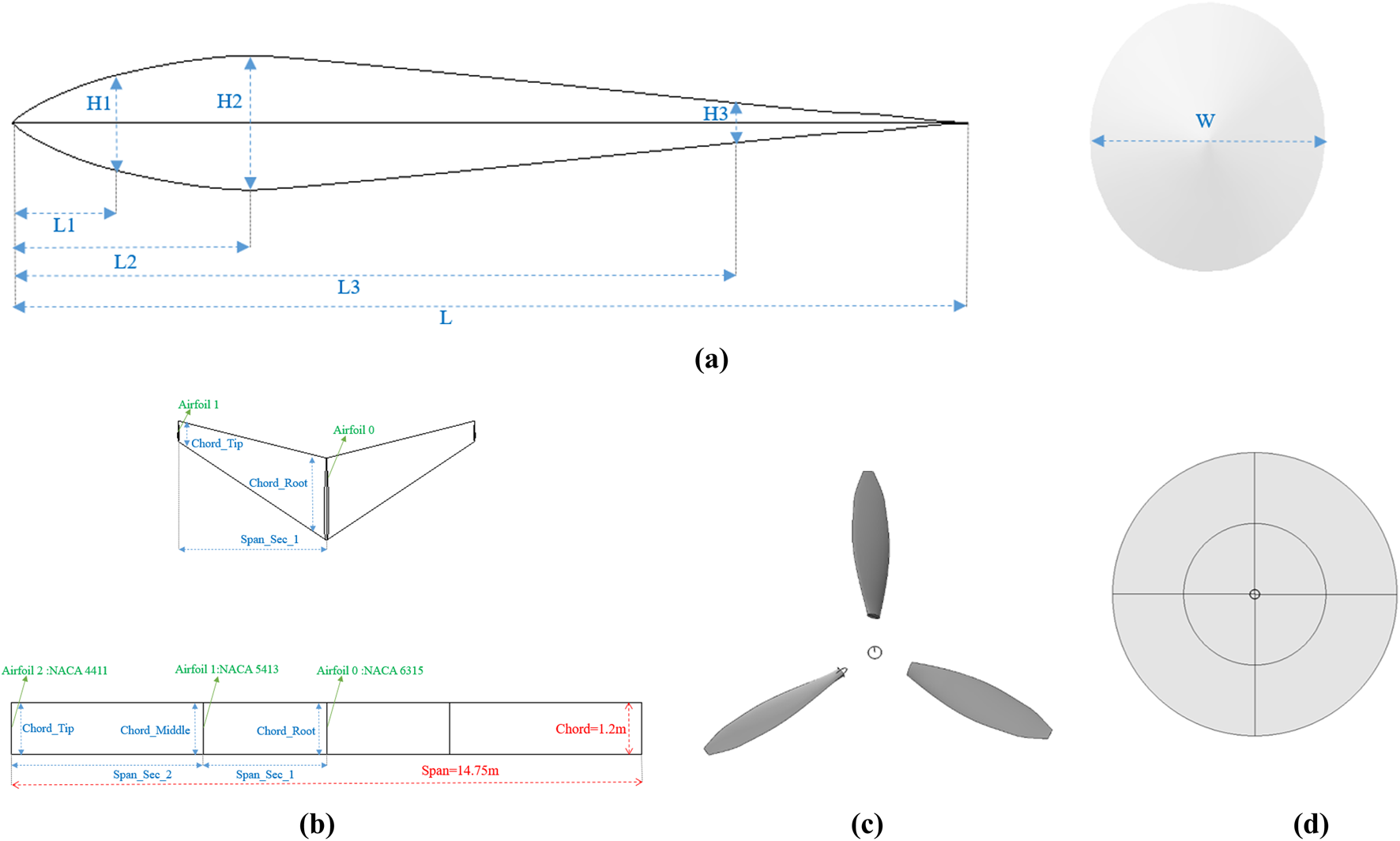
Parametric definition of model. (a) Fuselage model; (b) wing model; (c) propeller model; (d) disk model.
Wing modeling is implemented by Wing components, and its main parameters include Area, Span, Chord, Aspect Ratio, Taper Ratio, Sweep, Dihedral, Incidence and Twist. Figure 9b shows main wing is a straight wing with two segments of wings, which requires at least three wing shapes, three chord lengths and two spread lengths. The tail wing is a single-stage wing with a sweep angle and a dihedral angle. Its airfoil is defined by parameterization of the airfoil camber (Camber), The ratio of thickness to chord length (T/C) and maximum camber location (Camber Loc).
The propulsion system modeling includes two modes: the propeller mode (Blade Mode) and the actuator disk mode (Disk Mode), as respectively depicted in Figures 9c,d. In the propeller mode (Blade Mode), the Propeller component is utilized to define parameters such as the blade’s radial chord length, twist angle distribution, and airfoil distribution. This mode supports the import and export of Blade Element Momentum (BEM) files, facilitating collaborative design across multiple tools. This functionality was employed in the subsequent propeller reverse design.
The actuator disk mode (Disk Mode) simulates the aerodynamic interference effect of the propeller on the wing and fuselage and calculates the slipstream velocity increment by inputting parameters such as D, RPM, CT, and CP. This approach avoids the need for complex blade geometry modeling, thereby significantly reducing computational resource consumption.
For the aerodynamic analysis, the script file “.vspscript” defines parameters such as the angle of attack (Alpha), Mach number (Mach), and Reynolds number (ReCref) through the VSPAERO module, and specifies the VLM as the solution approach. After the calculation is completed, the geometric model file “.vsp” and the standardized aerodynamic report file “.polar” are automatically output. The file “.polar” contains key indicators such as Cl, Cd and induced drag coefficient Cdi. Additionally, the model can be visualized by calling the “vspviewer” program via the CMD interface.
This process achieves full closed-loop automation of “geometric modeling- aerodynamic calculation-result output” through a single script file “.vspscript”. Each iteration takes less than 1 minute, which represents two orders of magnitude more efficiently than the traditional CFD method, providing reliable technical support for the rapid optimization of eVTOL aerodynamic configurations. The model file “.vsp” also supports direct export to format files such as STL, STP, and IGS. This method is used in the subsequent CFD high-fidelity verification.
Surrogate Optimization
This study constructed an optimization framework centered around the Kriging surrogate model in Figure 10a. This framework realizes efficient optimization of eVTOL aerodynamic configurations through a multi-layer collaboration mechanism.
FIGURE 10
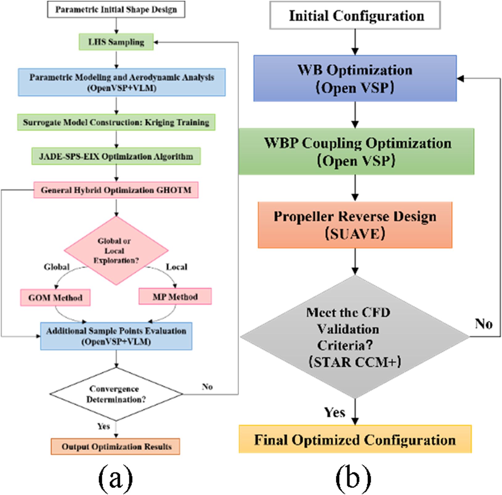
Framework of optimization methods and processes. (a) Surrogate optimization framework; (b) complete optimization process Flowchart.
In the initial sampling phase, an improved Latin hypercube sampling (LHS) method is employed to generate design space samples [42]. By integrating OpenVSP parametric modeling with VLM, aerodynamic evaluations and training dataset construction are completed within minutes. Subsequently, Gaussian process regression is utilized to establish a Kriging surrogate model [43], which characterizes the correlation between design variables and aerodynamic responses through nonlinear mapping relationships. This provides an efficient surrogate model for subsequent optimization processes.
The JADE-SPS-EIX algorithm [44] is employed as the optimization search algorithm, which introduces three innovations based on JADE [45]. Firstly, it adopts a dynamic parameter adaptation mechanism that adjusts the scaling factor (sf) and crossover probability (Cr) in real time using historical iteration data. Here, sf follows a Cauchy distribution, while Cr is updated based on a normal distribution derived from successful individuals, enabling the algorithm parameters to adaptively match the complex design space. Secondly, it constructs a Successful Parent Selection (SPS) strategy [46]. When the j individual in the population fails to produce a superior offspring in succession Q times, the algorithm forcibly selects a parent individual from the set of successful individuals (S) for mutation and crossover operations, thereby preventing the search from stagnation. Thirdly, it proposes an Eigenvector-based Crossover (EIX) operator [47, 48]. This operator constructs an eigenvector coordinate system through covariance matrix analysis and performs crossover operations within this system instead of the natural coordinate system. This approach allows the search direction to gradually approximate the feature space of the objective function, significantly enhancing the efficiency of solving coupled problems.
During the dynamic adding point and iterative updating phase, the Generalized Hybrid One-Two Stage Method (GHOTM) proposed in reference [44] is adopted to balance exploration and exploitation. This method employs a two-stage dynamic switching strategy: In the global exploration phase, based on the Generalized One Stage Method (GOM) [44], it comprehensively considers the predicted values of the surrogate model, prediction variances, and gradients of the objective function. It prioritizes regions with high uncertainty, low objective values, and smooth gradients as new sample points. When a potentially optimal region is detected, the algorithm automatically switches to the Minimize Prediction method (MP) [49] to perform local search. The method gradually narrows the search range centered around the current optimal solution for in-depth development. If the local search stagnates, the algorithm will automatically restart GOM for global exploration. To mitigate the impact of optimization boundary settings on the optimization results, a 10% adaptive boundary expansion method for the design space is employed.
This mechanism achieves an adaptive balance between global exploration breadth and local search depth by monitoring the optimization state in real time. The newly added sample points are validated twice by OpenVSP and VLM to update the surrogate model, forming an autonomous closed-loop iteration of “parametric modeling - surrogate optimization - convergence determination”. Through modular process design, the optimization framework cohesively integrates sampling, modeling, aerodynamic optimization and verification, ultimately achieving efficient optimization of complex aerodynamic configurations.
A Phased Optimization Strategy
This study adopts a phased collaborative aerodynamic design strategy in Figure 10b (“WB Optimization - WBP Coupling Optimization - Propeller Reverse Design - High-Fidelity CFD Validation”). This strategy systematically decouples complex aerodynamic coupling issues through hierarchical decomposition, significantly reducing the computational complexity of multivariable optimization. The first stage focuses on wing aerodynamic shape optimization, enhancing cruise efficiency through lift-to-drag ratio (L/D) maximization. The second stage introduces an actuator disk model to quantify propeller slipstream interference effects on the wing, employing a comprehensive performance target (η·L/D) as the optimization objective. The third stage performs reverse design to convert actuator disk parameters into propeller geometry model, with final validation conducted via high-fidelity CFD simulations to confirm the physical feasibility and engineering applicability of optimization results.
Optimization Results and Discussion
Wing-Body Optimization
To achieve the above goals, this study utilizes the Supernal S-A1 [50] (Tilting rotors fixed Lift propellers) model as a reference prototype and builds the baseline model as the optimization target in Figure 11a. Since this study focuses only on the cruise condition, the tilting propellers are modeled only in the propulsion state, ignoring the lift propeller interference in the non-working state. During the phase of WB optimization (Wing-Body), a simplified baseline model is adopted, which includes only the fuselage, main wing, and tail wing in Figure 11b. The geometric parameters of main wing are presented in Figure 9b.
FIGURE 11
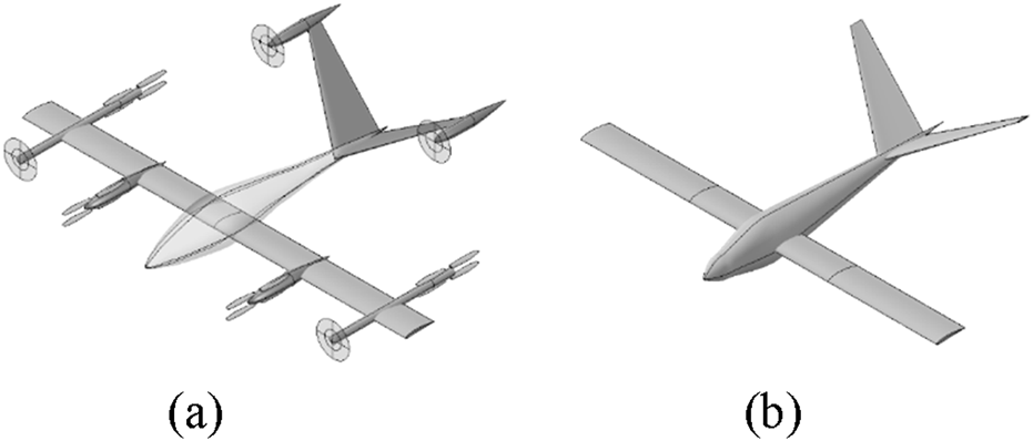
Schematic diagram of model in open VSP. (a) Complete reference model; (b) simplified baseline WB model.
The simplified baseline model references the actual flight conditions of the S-A1: flight altitude approximately H = 0.5 km, ρ = 1.16727 kg/m3, Ma = 0.169 (V = 57.18 m/s), Re = 4.39 × 10⁶, and α = 2°. The wing parametrization study is conducted with the optimization objective of maximum L/D. During the optimization process, the fuselage and tail configuration parameters (position and shape) remain fixed. Minor longitudinal adjustments (X-axis) of the wing position are permitted to maintain structural pitch moment characteristics, while minor vertical adjustments (Z-axis) are allowed to optimize ground effect performance. Aerodynamic configuration parameters of the wing include 23 design variables in Table 1. The pressure distribution is reconstructed and balances profile drag and induced drag through collaborative parameter adjustments. The mathematical model of aerodynamic optimization is established as Equation 16.
TABLE 1
| Variable | Init | Scope | Opt |
|---|---|---|---|
| X_location/m | 0 | [−0.25,0.25] | 0.276 |
| Incidence/° | 0 | [−3,3] | 2.152 |
| Chord_Middle/m | 1.2 | [1.1,1.3] | 1.220 |
| Sweep_Sec_1/° | 0 | [−5,5] | 0.603 |
| Twist_Sec_1/° | 0 | [−3,3] | −0.280 |
| Span_Sec_2/m | 4.5 | [4,5] | 4.924 |
| Dihedral_Sec_2/° | 0 | [−3,3] | −0.205 |
| Airfoil 0_T/C | 0.15 | [0.13,0.17] | 0.15 |
| Airfoil 0_CamberLoc/m | 0.3 | [0.2,0.4] | 0.276 |
| Airfoil 1_ Camber | 0.05 | [0.03,0.07] | 2.152 |
| Airfoil 2_T/C | 0.11 | [0.09,0.13] | 1.220 |
| Airfoil 2_CamberLoc/m | 0.4 | [0.3,0.5] | 0.603 |
| Z_location/m | 0 | [−0.4,0.4] | −0.096 |
| Chord_Root/m | 1.2 | [1,1.4] | 1.330 |
| Area_Sec_1/m2 | 3.45 | [3.2,3.7] | 3.724 |
| Dihedral_Sec_1/° | 0 | [−3,3] | −0.575 |
| Chord_Tip/m | 1.2 | [1.15,1.25] | 1.133 |
| Sweep_Sec_2/° | 0 | [−5,5] | 4.218 |
| Twist_Sec_2/° | 0 | [−3,3] | −0.140 |
| Airfoil 0_ Camber | 0.06 | [0.04,0.08] | 0.06 |
| Airfoil 1_T/C | 0.13 | [0.11,0.15] | −0.096 |
| Airfoil 1_CamberLoc | 0.4 | [0.3,0.5] | 1.330 |
| Airfoil 2_ Camber | 0.04 | [0.02,0.06] | 3.724 |
Variables for WB model optimization.
Among them, Clwing and Clwing,0 represent the lift coefficients before and after optimization, while Swing and Swing,0 denote the wing areas before and after optimization. Constraints include a lower limit for the Cl ≥ 0.638 and a fluctuation range for wing projected area (Sw ± 10%). Constraint violations are managed through a penalty function approach, with penalty factors set to 30 for area constraints and 600 for lift constraints to align with the objective function magnitude. LHS is employed to generate 30 initial samples, with a maximum evolutionary iteration (Maxit = 100) and a population size (NP = 100). Figure 14a shows efficient coordinated adjustment of aerodynamic configuration parameters is achieved through 11 rounds of adding point, including the coordinated iteration of global GOM and local MP. The sampling process takes 9 min, and the optimization process takes 3 h and 20 min, which indicates that the calculation time for a single working condition is less than 1 minute
In Table 1, optimization results indicate that the value of X_location 0.276 m exceeds the boundary value 0.25 by 10%, which is in line with the design space adaptive expansion mechanism. And the wingspan increased from 14.75m to 15.69 m (+6.4%), the mean chord length extended to 1.23 m (+2.1%), and a 0.603° sweep angle along with a −0.575° dihedral angle were introduced. For airfoil parameters, thickness ratio (T/C) of the outer-section airfoil (Airfoil 2) reduced from 0.11 to 0.10, while the camber value (Camber) increased from 0.04 to 0.06. These modifications reconstructed the leading-edge suction peak and trailing-edge pressure recovery gradient as shown in Figure 12. In Table 2, the optimized L/D improved from 28.9 to 31.6 (+9.3%), the Cl increased by 35.1% (from 0.638 to 0.862), and the wing area (Sw) only expanded by 7.5%, satisfying all constraints.
FIGURE 12
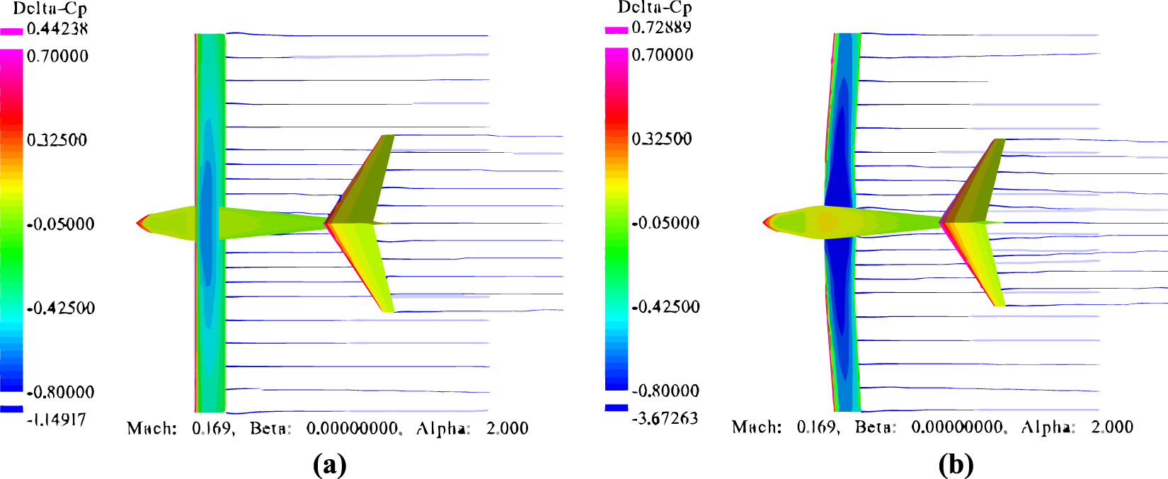
Pressure difference contour plots for WB model. (a) Baseline WB model; (b) optimized WB model.
TABLE 2
| Shape | L/D | C l | S w (m2) |
|---|---|---|---|
| Baseline | 28.9 | 0.638 | 17.70 |
| Optimization | 31.6 | 0.862 | 19.03 |
| Variation | 9.3% | 35.1% | 7.5% |
Variation of the optimization objective and constraints for WB model.
Wing-Body-Propeller Coupling Optimization
Based on the optimized WB configuration, ADT is employed to simplify the propeller into a disk. This approach is further used to conduct the propeller-wing coupling optimization through a new baseline WBP model (Wing-Body-Propeller), as shown in Figure 13. And the comprehensive propulsion efficiency and lift-to-drag ratio (η·/L/D) are taken as the optimization objectives, which aims to achieve the collaborative optimization of energy conversion efficiency and cruise aerodynamic performance.
FIGURE 13
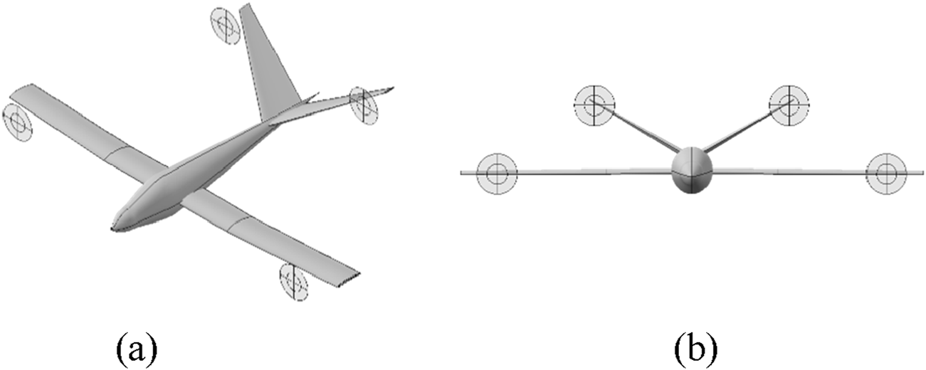
Baseline WBP model. (a) Side view; (b) front view.
With the optimized drag coefficient Cd = 0.0273 and drag Equation 17, the total cruise drag F is calculated as 935 N.
When total propulsion efficiency ηtotal = 0.75 is set, the thrust Equation 18 yields a total required total thrust Ttotal = 1246 N. It is subsequently distributed equally across four disks to obtain the single disk thrust T = 311.5 N.
During the optimization process, the shape and location of the wing remain constant. The design variables cover a total of 7 parameters, including the rotational speed (RPM), diameter (D), location and rotation angle of disks on the main wing and the tail wing, as shown in Table 3. With single disk thrust T = 311.5 N established as a fixed boundary condition, the CT is derived using disk D and RPM as design variables. A dual-constraint mechanism governs CP selection: first, an empirical feasible range CP∈[0.04,0.08] is defined based on electric propulsion system efficiency characteristics, and then the theoretical boundary CPEquation 19 is inversely deduced by the efficiency Equation.
TABLE 3
| Variable | Init | Scope | Opt |
|---|---|---|---|
| D/m | 1.36 | [1.2,1.5] | 1.416 |
| Y_location/m | 6.6 | [6,7.2] | 6.576 |
| Z_location_Vtail/m | 2.3 | [2.1,2.5] | 2.144 |
| RPM | 2,500 | [2000,3,000] | 2,398 |
| Y_rotation/° | 0 | [-5,5] | 2.144 |
| Z_location/m | −0.125 | [-0.4,0.2] | 0.015 |
| Y_rotation_Vtail/° | 0 | [-5,5] | −4.129 |
Variables for WBP model optimization.
The intersection of these constraints defines the physically realizable parameter space. During optimization iterations, the value of CP needs to be secondary validation. When η > 0.9 or CP is out of bounds, a forced penalty function of η = 0.5 is applied to ensure stable optimization. Consequently, the mathematical model of integrated propeller-wing aerodynamic optimization is established as Equation 20
Figure 14b shows the WBP optimization is achieved through 8 rounds of adding points, including the coordinated iteration of global GOM and local MP. The sampling process (30 samples) takes 7 min, and the optimization process (200 samples) takes 1 h and 50 min, which reveals that the calculation time for a single working condition does not exceed 1 min.
FIGURE 14
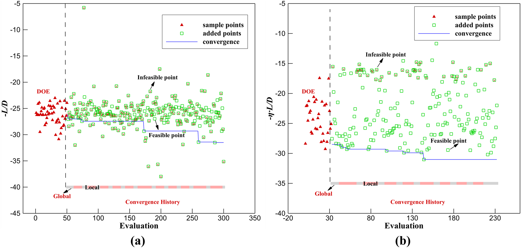
The optimization convergence process. (a) WB model; (b) WBP model.
Table 3 shows that after optimization, the vertical position of the disk (Z_location) is moved up to 0.015 m (+0.14 m), the D is increased to 1.416 m (+4.1%), the rotation angle (Y_rotation) is adjusted to 3.736°, and the rotational speed is reduced to 2398 RPM. The optimized slipstream coverage pattern in Figure 15 reveals a lateral shift of the slipstream core toward the wing’s mean camber line. Concurrently, the leading-edge suction peak ΔCp_min undergoes pressure recovery from −7.474 to −3.692, the pressure gradient becomes more gradual, and the flow separation is effectively suppressed, which directly correspond to the 24.5% reduction of Cdi in Table 4. This phenomenon conforms to the slipstream velocity correction Equation 21 in momentum theory.
FIGURE 15
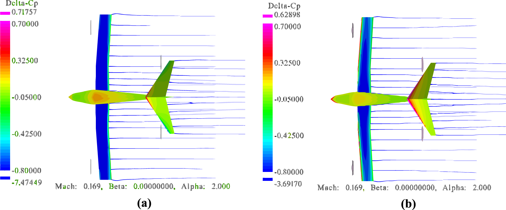
Pressure difference contour plots for WBP model. (a) Baseline WBP model; (b) optimized WBP model.
TABLE 4
| Shape | η·L/D | C l | C di | C T | C P |
|---|---|---|---|---|---|
| Basic Shape | 27.21 | 0.946 | 0.0102 | 0.0449 | 0.0567 |
| Optimized Shape | 31.02 | 0.907 | 0.0077 | 0.0416 | 0.0494 |
| Variation | +14% | −4.1% | −24.5% | −7.3% | −14.8% |
Variation of the optimization objective and constraints for WBP model.
The increase in diameter reduces both CT and slipstream velocity . Despite a 4.1% reduction in Cl attributed to slipstream coverage adjustment, propulsive efficiency η demonstrates a 6.25% improvement. The η·L/D increases from 27.21 to 31.02 (+14%). The results show that by coordinating the location and diameter of the disk, the slipstream gain and aerodynamic interference loss can be effectively balanced, significantly improving the energy utilization efficiency of the eVTOL cruise phase.
Propeller Reverse Design
Based on the propeller-wing coupling optimization results, the SUAVE platform is used to realize the reverse reconstruction of disk parameters to three-dimensional propeller geometry based on Betz-BEM theory. The input parameters are shown in Table 5, and the radial distribution of the optimal propeller geometric characteristic parameters in this design state is shown in Figure 16a. The design propeller is evaluated by OpenVSP’s MRF-VLM method, and its pressure difference coefficient contour and vorticity contour are shown in Figures 16b,c.
TABLE 5
| Design parameter | Value | Design parameter | Value |
|---|---|---|---|
| Thrust/N | 311.5 | Hub Radius/m | 0.1416 |
| Tip Radius/m | 0.708 | RPM | 2,398 |
| Freestream Velocity/m/s | 57.18 | Lift Coefficient | 0.5 |
| Flight Altitude/m | 500 | Blade Airfoil | NACA4412 |
Reverse design parameter values of propeller.
FIGURE 16

Geometric parameters and simulation diagram based on MRF-VLM for propeller. (a) Radial distribution characteristics; (b) pressure difference contour; (c) vorticity contour.
The single propeller thrust calculated by MRF-VLM method is 301.0 N, which deviates 3.4% from SUAVE’s BEM -based design target value of 311.5 N. BEM provides rapid preliminary design and MRF-VLM enables three-dimensional flow verification, forming a design-validation closed loop. This validates the efficacy of the BEM-MRF hybrid design in eVTOL propeller inverse design.
High-Fidelity Validation
To systematically evaluate the physical rationality of the optimization design, STAR-CCM+ is used to carry out MRF-RANS numerical verification. For isolated propellers, a rotating and static domain partition grid is constructed in Figure 17a. Figure 17b shows that a total grid volume of 4.76 million is generated using non-structural grids, and grid refine is performed on the propeller blade tips to capture the boundary layer effect. Figure 17c shows its pressure coefficient cloud diagram.
FIGURE 17

Schematic diagram of MRF-Based propeller aerodynamics simulation. (a) Fluid domain division; (b) surface grid; (c) pressure coefficient contour.
The calculation results in Table 6 show that the thrust and torque of the isolated propeller are 5.2% lower and 9.1% higher respectively than the MRF-VLM results of VSPAERO. Although the MRF-VLM method has limitations of insufficient viscosity effect simulation, the design of the propeller involves multiple parameters, and the iteration can be completed within 5 min in the conceptual design stage. Compared with the calculation time of 1 h for a single working condition of MFR-RANS, the calculation efficiency has increased by more than 10 times.
TABLE 6
| Solver | Thrust/N | Error | Torque/N·m | Error |
|---|---|---|---|---|
| STAR-CCM+ | 286 | 5.2% | 98 | 9.1% |
| VSPAERO | 301 | 87 |
Comparison of propeller performance simulation results from different solvers.
STAR-CCM+ conducted MRF-RANS numerical simulations for the three configurations, including baseline WB, optimized WB and optimized WBP. Among them, the leading edge, trailing edge of the wing and the propeller area all adopted refinement processing. The total number of grids WB is 10.5 million, and the grids reached 14.58 million with adding the propeller rotation domain. The surface grid divisions of the WB and WBP are shown in Figures 18a,b, and the rotation domain and far-field surface grid are shown in Figures 18b,c.
FIGURE 18

Grid distribution plot in STAR-CCM+. (a) Optimized BW surface grid; (b) optimized BWP surface grid; (c) far-field grid.
In Figure 19, the STAR-CCM+ computational results reveal the significant impact of propeller slipstream on the aerodynamic characteristics of the wing. Compared to the baseline WB, optimized WB exhibits an expanded leading-edge negative pressure extending chordwise region. When the propeller slipstream is further introduced in the optimized WBP configuration, the leading-edge negative pressure zone expands even more. This trend of gradual negative pressure region enlargement is consistent with the evolutionary patterns of pressure difference contour plots observed during two optimization stages: WB optimization (Figure 12a,b) and WBP coupling optimization (Figure 15) based on the VLM.
FIGURE 19

Pressure coefficient contour plot in STAR-CCM+. (a) Baseline WB; (b) optimized WB; (c) optimized WBP.
The quantitative data in Table 7 shows that the Cl of the WBP configuration calculated by STAR-CCM+ increases by 15.6%, and the L/D increases by 18.4%, which is consistent with the trend of slipstream enhancement predicted by VSPAERO. Although the Cl errors between the two solvers is 9.7%, both effectively capture the slipstream enhancement on aerodynamic performance. Aerodynamic curves in Figure 20 further demonstrate that while numerical discrepancies exist in Cl and L/D predictions across different angles of attack, the variation trends in aerodynamic characteristics show strong agreement between STAR-CCM+ and VSPAERO. The calculation time of this high-fidelity RANS method for a single working condition of the WB model and the WBP model is 1 h and 1 h 20 min respectively. Compared with this method, the calculation efficiency of the VLM method has increased by 80–160 times.
TABLE 7
| Solver | Opt WB Cl | Opt WB L/D | Opt WBP Cl | Opt WBP L/D |
|---|---|---|---|---|
| STAR-CCM+ | 0.717 | 17.4 | 0.829 | 20.6 |
| VSPAERO | 0.862 | 31.6 | 0.907 | 36.5 |
Comparison of propeller-wing coupled aerodynamic analysis simulation results.
FIGURE 20
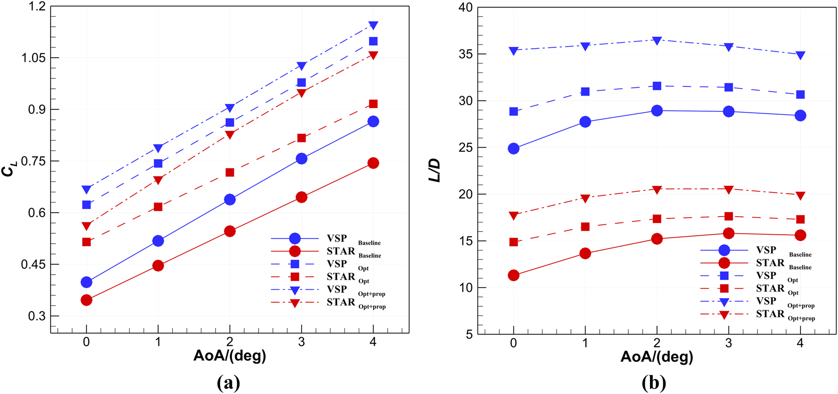
Comparison of aerodynamic results of the different models. (a)CL at different angles of attack; (b)L/D at different angles of attack.
Conclusion
This study demonstrates that the OpenVSP platform, combined with a surrogate model - based optimization framework, provides an efficient solution for aerodynamic configuration design of eVTOL aircraft. Overall, the parametric modeling and phased collaborative aerodynamic design strategy based on OpenVSP effectively balances efficiency and accuracy, enabling efficient multivariable optimization of the eVTOL cruise configuration, accelerating the design cycle, ensuring engineering reliability, and offering a scalable solution for future urban air traffic applications. The following conclusions can be drawn:
(1) OpenVSP achieves rapid parametric modeling through its built - in parametric component library (such as fuselage, wing, and actuator disk) and script driver framework. In terms of calculation accuracy, the VLM in OpenVSP has good consistency with experimental data: The Cl error of the NACA 0015 airfoil at a low angle of attack is within 14%, and the Cl error of the ADT - VLM method of the PROWIM model is less than 3% and the Cd error is less than 12.2% when α = 6°–8°.
(2) During the WB optimization stage, by adjusting 23 geometric parameters (including wing position, shape and airfoil distribution), L/D was increased by 9.3%. The optimization process efficiently achieves the fully automatic integration of modeling, meshwork and aerodynamic analysis, shortening the single iteration cycle to the minute level. The optimization framework combining the Kriging surrogate model and the phased collaborative aerodynamic design strategy (WB optimization - WBP coupling optimization) effectively completed the aerodynamic optimization of the eVTOL cruise configuration: By optimizing seven key parameters such as the impeller diameter and position, the comprehensive performance index η·L/D increased by 14%, and the single - condition evaluation cost was reduced to within 1 min.
(3) The reverse design results of the propeller based on Betz - BEM theory show that the thrust error of the calculation results between MRF - VLM and BEM is only 3.4%. Although the Cl error of the optimized WBP model and high - fidelity RANS simulation is 9.7%, the changing trend of aerodynamic characteristics is highly consistent, and the calculation time of VLM is 80–160 times faster than that of RANS.
In conclusion, the proposed method not only plays a significant role in the current eVTOL aerodynamic design but also lays a foundation for future applications in urban air traffic, where iterative exploration and physical feasibility are of crucial importance.
Statements
Data availability statement
The original contributions presented in the study are included in the article/supplementary material, further inquiries can be directed to the corresponding author.
Author contributions
ZL participated in research design, programming, surrogate model training, data analysis, drawing, and manuscript writing. YD is responsible for reviewing and editing manuscripts, and providing valuable suggestions for article structure and graphic creation. MS provided assistance in verifying the optimization results, while JW, KZ, CJ, and JZ proposed improvement suggestions for the optimization model. All authors contributed to the article and approved the submitted version.
Funding
The author(s) declare that financial support was received for the research and/or publication of this article. The work is funded by The National Natural Science Foundation of China (Project Number: 12202284).
Acknowledgments
The authors would like to thank Haoliang Yu from Northwestern Polytechnical University for his inspiring comments on the work.
Conflict of interest
The authors declare that the research was conducted in the absence of any commercial or financial relationships that could be construed as a potential conflict of interest.
Generative AI statement
The author(s) declare that no Generative AI was used in the creation of this manuscript.
References
1.
Patterson MD Antcliff KR Kohlman LW . A Proposed Approach to Studying Urban Air Mobility Missions Including an Initial Exploration of Mission Requirements. In: Annual Forum and Technology Display (2018).
2.
Roy S Maheshwari A Crossley WA DeLaurentis DA . Future Regional Air Mobility Analysis Using Conventional, Electric, and Autonomous Vehicles. J Air Transportation (2021) 29(3):113–26. 10.2514/1.D0235
3.
Daskilewicz M German B Warren M Garrow LA Boddupalli SS Douthat TH . Progress in Vertiport Placement and Estimating Aircraft Range Requirements for EVTOL Daily Commuting. 2018 Aviation Technology, Integration, and Operations Conference. Atlanta, Georgia: AIAA2018–2884. (2018). 10.2514/6.2018-2884
4.
Brown A Harris WL . Vehicle Design and Optimization Model for Urban Air Mobility. J Aircraft (2020) 57(6):1003–13. 10.2514/1.C035756
5.
Brelje BJ Martins JRRA . Electric, Hybrid, and Turboelectric fixed-wing Aircraft: A Review of Concepts, Models, and Design Approaches. Prog Aerospace Sci (2019) 104:1–19. 10.1016/j.paerosci.2018.06.004
6.
Ronzheimer A . Aircraft Geometry Parameterization with high-end CAD-Software for Design Optimization. In: Proceedings ECCOMAS (2012).
7.
Bhise TA Course MD . Conceptual Design and Parametric Modeling of the Aircraft Wing (2020). 10.13140/RG.2.2.29170.94400
8.
Lyu Z Martins JRRA . Aerodynamic Design Optimization Studies of a blended-wing-body Aircraft. J Aircraft (2014) 51(5):1604–17. 10.2514/1.C032491
9.
Li L Bai J Guo T . Aerodynamic Optimization Design of the Supersonic Aircraft Based on Discrete Adjoint Method. J Northwest Polytechnical Univ (2017) 35(5):843–9. 10.3390/aerospace10050420
10.
Bryant AH Walters DK . Developing a Small-Scale Propeller Thrust Model Using Experimentation and CFD. AIAA Scitech 2021 Forum. AIAA2021–1307. Virtual Event. (2021) 10.2514/6.2021-1307
11.
Liu X Zhao D Oo NL . Comparison Studies on Aerodynamic Performances of a Rotating Propeller for small-size Uavs. Aerospace Sci Technology (2023) 133:108148. 10.1016/j.ast.2023.108148
12.
Sinnige T van Arnhem N Stokkermans TCA Eitelberg G Veldhuis LLM . Wingtip-Mounted Propellers: Aerodynamic Analysis of Interaction Effects and Comparison with Conventional Layout. J Aircraft (2019) 56(1):295–312. 10.2514/1.c034978
13.
Li P Zhao QJ . CFD Calculations on the Interaction Flow Field and Aerodynamic Force of tiltrotor/wing in Hover. Acta Aeronautica et Astronautica Sinica (2014) 5(2):361–71. 10.7527/S1000-6893.2013.0220
14.
Xu J Yu J Lu X Long Z Xu Y Sun H . Aerodynamic Performance and Numerical Analysis of the Coaxial Contra-rotating Propeller Lift System in Evtol Vehicles. Mathematics (2024) 12(7):1056. 10.3390/math12071056
15.
Dang TQ . Simulations of propeller/airframe Interference Effects Using an Euler Correction Method. J Aircraft (1989) 26(11):994–1001. 10.2514/3.45872
16.
Thom A Duraisamy K . Computational Investigation of Unsteadiness in Propeller Wake–Wing Interactions. J Aircraft (2013) 50(3):985–8. 10.2514/1.C031866
17.
Whitfield DL Jameson A . Euler Equation Simulation of propeller-wing Interaction in Transonic Flow. J Aircraft (1984) 21(11):835–9. 10.2514/3.45052
18.
Benaouali A Kachel S. A Surrogate-based Integrated Framework for the Aerodynamic Design Optimization of a Subsonic Wing Planform Shape. Proc Inst Mech Eng G: J Aerospace Eng (2018) 232(5):872–83. 10.1177/0954410017699007
19.
Rao KS Abhilasha AN Das A Sivapragasam M . Aerodynamic Shape Optimization at Low Reynolds Number Using multi-level Hierarchical Kriging Models. Optimization Eng (2025) 26(1):479–505. 10.1007/s11081-024-09915-2
20.
Piotrowski MG Zingg DW . Investigation of a Smooth Local Correlation-Based Transition Model in a Discrete-Adjoint Aerodynamic Shape Optimization Algorithm. AIAA Scitech 2022 Forum. San Diego, CA & Virtual: AIAA2022–1865. (2022) 10.2514/6.2022-1865
21.
Zhang W Tan M Liu YF Nie YB Luan Y . Wing Design and Adaptive Optimization of a Compound Drone. Phys Gases (2024) 9(2):54–65. (in Chinese). 10.19527/j.cnki.2096-1642.1091
22.
Abdul-Kaiyoom MAS Yildirim A Martins JRRA . Coupled Aeropropulsive Design Optimization of an Over-wing Nacelle Configuration. J Aircraft (2025) 62(1):94–116. 10.2514/1.C037678
23.
Chauhan SS Martins JRRA . Rans-Based Aerodynamic Shape Optimization of a Wing Considering propeller–wing Interaction. J Aircraft (2021) 58(3):497–513. 10.2514/1.C035991
24.
Pedreiro LN . Estudo E Otimização De Uma Asa Sob Efeito De Hélice Na Configuração Tractor Para Redução De Arrasto (2017).
25.
Alba C Elham A German BJ Veldhuis LL . A Surrogate-based multi-disciplinary Design Optimization Framework Modeling wing–propeller Interaction. Aerospace Sci Technology (2018) 78:721–33. 10.1016/j.ast.2018.05.002
26.
Paek SK Chae S Kang HJ . Development of Mission Analysis Tool for Evtol Aircrafts of Lift-Tilt Concept. J Korean Soc Aeronaut & Space Sci (2021) 49(10):859–70. 10.5139/JKSAS.2021.49.10.859
27.
Sun ZY Wang Q Qiao W Fu C Zheng YF Song JY . Research on the Analysis Method of Distributed propeller-wing Design of Electric Aircraft. Aeronaut Sci & Technology (2024) 35(01):53–64 (in Chinese). 10.19452/j.issn1007-5453.2024.01.006
28.
Yu HL Lei T Zhang XY Zhang XB . A Fast Multidisciplinary Parameter Estimation Method for Distributed Electric Propulsion Aircraft. Aeronaut Sci Technolog (2024) 35(01):65–74 (in Chinese). 10.19452/j.issn1007-5453.2024.01.007
29.
Sheridan CN Pham DD Whiteside S . Evaluation of Vspaero Analysis Capabilities for Conceptual Design of Aircraft with Propeller-Blown Wings. (2021). AIAA 2021–2510. Virtual Event. 10.2514/6.2021-2510
30.
Wu J Gao F Li S Yang F . Conceptual Design and Optimization of Distributed Electric Propulsion General Aviation Aircraft. Aerospace (2023) 10(5): 387. 10.3390/aerospace10050387
31.
Anderson JD . Fundamentals of Aerodynamics(Seventh Edition). New York: McGraw Hill Higher Education (2024).
32.
Katz J Plotkin A . Low-Speed Aerodynamics. Cambridge: Cambridge University Press (2001).
33.
Drela M . Flight Vehicle Aerodynamics. MIT press (2014).
34.
Cheng ZY Yang YX Zhang XC Yu LF Ye B . Rapid Evaluation Method for Aerodynamic Characteristics of Distributed Electric Propulsion Aircraft Concept Scheme. J Beijing Univ Aeronautics Astronautics (2023) 49(11):3047–58. (in Chinese). 10.13700/j.bh.1001-5965.2021.0771
35.
Miranda LR Elliot RD Baker WM . A Generalized Vortex Lattice Method for Subsonic and Supersonic Flow Applications. (1977).
36.
Resende GJ Malatesta V Savio MC Castro BM . Wing’s Aerodynamic Characteristics due to Distributed Propulsion over the Wingspan. J Braz Soc Mech Sci Eng (2023) 45(9):495. 10.1007/s40430-023-04413-5
37.
Gudmundsson S . General Aviation Aircraft Design: Applied Methods and Procedures. Butterworth-Heinemann (2013).
38.
Conway JT . Analytical Solutions for the Actuator Disk with Variable Radial Distribution of Load. J Fluid Mech (1995) 297:327–55. 10.1017/s0022112095003120
39.
Johnson W . Helicopter Theory. Princeton: Princeton University Press (1980).
40.
McAlister KW . NACA 0015 Wing Pressure and Trailing Vortex Measurements. Technical Paper of National Aeronautics and Space Administration, Office of Management, Scientific and Technical Information Program. NASA-TP-3151. (1991).
41.
Veldhuis LLM . Propeller Wing Aerodynamic Interference. Delft: Delft University of Technology (2005).
42.
Jin R Chen W Sudjianto A . An Efficient Algorithm for Constructing Optimal Design of Computer Experiments. J Stat Plann inference (2005) 134(1):268–87. 10.1016/j.jspi.2004.02.014
43.
Sacks J Welch WJ Michell TJ Wynn HP . Design and Analysis of Computer Experiments. Stat Sci (1989) 4(4):409–35. 10.1214/ss/1177012413
44.
Zhu XQ . Research on Flight Vehicle Shape Optimization Design Algorithms and multi-output Surrogate Model. Xi’an: Northwestern Polytechnical University (2019).
45.
Zhang J Sanderson AC . JADE: Adaptive Differential Evolution with Optional External Archive. IEEE Trans Evol Comput (2009) 13(5):945–58. 10.1109/TEVC.2009.2014613
46.
Guo SM Yang CC Hsu PH Tsai JSH . Improving Differential Evolution with a successful-parent-selecting Framework. IEEE Trans Evol Comput (2015) 19(5):717–30. 10.1109/TEVC.2014.2375933
47.
Guo SM Yang CC . Enhancing Differential Evolution Utilizing Eigenvector-based Crossover Operator. IEEE Trans Evol Comput (2014) 19(1):31–49. 10.1109/TEVC.2013.2297160
48.
Wang Y Li HX Huang T Li L . Differential Evolution Based on Covariance Matrix Learning and Bimodal Distribution Parameter Setting. Appl Soft Comput (2014) 18:232–47. 10.1016/j.asoc.2014.01.038
49.
Jones DR . A Taxonomy of Global Optimization Methods Based on Response Surfaces. J Glob optimization (2001) 21:345–83. 10.1023/a:1012771025575
50.
Kim DH Lee JH Hwang HY . Aerodynamic Analysis, Required Power and Weight Estimation of a Compound (Tilt Rotor+ Lift+ Cruise) Type Evtol for Urban Air Mobility Using Reverse Engineering Techniques. J Adv Navigation Technology (2021) 25(1):17–28. 10.12673/JANT.2021.25.1.17.c
Summary
Keywords
eVTOL, vortex lattice method, parametric modeling, surrogate optimization, aerodynamic configuration
Citation
Du Y, Liu Z, Shen M, Wu J, Zhang K, Jiang C and Zhong J (2025) An Efficient Parametric Modeling, Evaluation and Optimization Strategy for Aerodynamic Configuration Design of eVTOL Aircraft. Aerosp. Res. Commun. 3:14986. doi: 10.3389/arc.2025.14986
Received
29 May 2025
Accepted
18 July 2025
Published
07 August 2025
Volume
3 - 2025
Updates
Copyright
© 2025 Du, Liu, Shen, Wu, Zhang, Jiang and Zhong.
This is an open-access article distributed under the terms of the Creative Commons Attribution License (CC BY). The use, distribution or reproduction in other forums is permitted, provided the original author(s) and the copyright owner(s) are credited and that the original publication in this journal is cited, in accordance with accepted academic practice. No use, distribution or reproduction is permitted which does not comply with these terms.
*Correspondence: Yiming Du, duyiming@sau.edu.cn
Disclaimer
All claims expressed in this article are solely those of the authors and do not necessarily represent those of their affiliated organizations, or those of the publisher, the editors and the reviewers. Any product that may be evaluated in this article or claim that may be made by its manufacturer is not guaranteed or endorsed by the publisher.