Abstract
Physics-informed neural networks (PINNs) have emerged as an effective tool for solving both forward and inverse partial differential equation (PDE) problems. However, their application in large-scale problems is limited due to their expensive computational cost. In this study, we employed an overlapping domain decomposition technique to enable the spatial-temporal parallelism in PINNs to accelerate training. Moreover, we proposed a rescaling approach for PINN inputs in each subdomain, which is capable of migrating the spectral bias in vanilla PINNs. We demonstrated the accuracy of the PINNs with overlapping domain decomposition (overlapping PINNs) for spatial parallelism using several differential equations: a forward ODE with a high-frequency solution, a two-dimensional (2D) forward Helmholtz equation, and a 2D inverse heat conduction problem. In addition, we tested the accuracy of overlapping PINNs for spatial-temporal parallelism using two nonstationary PDE problems, i.e., a forward Burgers’ equation and an inverse heat transfer problem. The results demonstrate (1) the effectiveness of overlapping PINNs for spatial-temporal parallelism when solving forward and inverse PDE problems, and (2) the rescaling technique proposed in this work is able to migrate the spectral bias in vanilla PINNs. Finally, we demonstrated that the overlapping PINNs achieve approximately efficiency with up to 8 GPUs using the example of the inverse time-dependent heat transfer problem.
Introduction
Physics-informed neural networks (PINNs) [1] have drawn extensive attention in a wide range of disciplines as a new scientific computing paradigm [2–10]. For instance, Cai et al. solved heat transfer problems using PINNs [11], Mao et al. proposed an adaptive sampling method based on the predicted gradients and residues to improve the accuracy of PINNs for PDEs with sharp solutions [12], and Lu et al. employed the PINNs for topology optimisation with partial differential equation (PDE) constraints [13, 14], just to name a few.
Despite the success of PINNs in solving both forward and inverse PDEs in various disciplines, their application to real-world, large-scale problems has been limited due to their high computational cost, especially in cases described by time-dependent PDEs [15]. Numerous approaches have been developed to accelerate the training of PINNs. Yu et al. proposed using the gradient of the equation to reduce the number of training points in PINNs, and thus enhance their convergence [4]. Jagtap et al. employed an adaptive activation function to accelerate the convergence of PINNs [16]. Another way to enhance the computational efficiency of PINNs is parallel computing. Inspired by the parallel computing approaches such as domain decomposition in conventional numerical methods, several PINN approaches based on the domain decomposition have also been developed [17]. Meng et al. developed parallel PINNs which enable the temporal parallelism of PINNs to solve long-term integration problems [18]. Furthermore, Jagtap et al. proposed conservative PINNs (cPINNs), which used a non-overlapping domain decomposition to enable spatial parallelism in PINNs when solving large-scale PDE problems [19]. Moreover, Jagtap et al. developed extended PINNs (xPINNs) based on the non-overlapping domain decomposition to enable spatial-temporal parallelism when solving forward and inverse PDE problems [20]. In cPINNs, the coupling condition at interfaces that separate different subdomains is the continuity of the data along with the normal flux. In the original xPINNs, only the continuity of the data is imposed at interfaces that separate different subdomains. Generally, the computation of the flux in cPINNs depends on the first derivative of the solution to the PDE at hand, which is computationally expensive especially for high-dimensional problems in PINNs if automatic differentiation is used. Hence, xPINNs are more attractive than cPINNs because there is no need to compute the derivative of the solution. However, Hu et al. pointed out that the imposition of continuity of the first derivative of the solution improves the training and generalisation of xPINNs [21, 22].
In addition to the aforementioned non-overlapping domain decomposition approaches, the overlapping domain decomposition is also a popular approach for parallel computing in conventional numerical methods [23]. Recently, PINNs with overlapping domain decomposition have been employed to solve unsteady inverse flow problems with both spatial and temporal parallelism [24]. However, the effectiveness of this approach for other PDE problems, such as forward PDEs, has not yet been demonstrated. Also, the computational efficiency of PINNs with overlapping domain decomposition has been tested on multiple CPUs in [24]. Generally, the GPUs are more efficient and thus more widely used in the training of PINNs. The efficiency of PINNs with overlapping domain decomposition on multiple GPUs remains unclear.
In this study, we utilised overlapping domain decomposition in PINNs (overlapping PINNs) to enable the spatial-temporal parallelism and enhance computational efficiency in PINN training. We also proposed a rescaling technique for overlapping PINNs to address the spectral bias in the vanilla PINNs. Furthermore, we tested the computational efficiency of overlapping PINNs on multiple GPUs using nonstationary PDE problems. The rest of the article is organised as follows: we introduce overlapping PINNs with rescaling in Section Methodology, a series of numerical experiments are presented in Section Results and Discussion, and this study is summarised in Section Summary.
Methodology
In this section, we first review the physics-informed neural networks (PINNs) for solving forward and inverse PDE problems, and we then introduce the overlapping domain decomposition approach for spatial-temporal parallelism in PINNs.
Physics-Informed Neural Networks
For any general partial differential equation (PDE) expressed aswhere denotes any differential operator, and are the spatial and temporal coordinates, respectively, and is either a known or unknown parameter/field that defines the operator. In forward PDE problems, is known, and we would like to find the solution to Equation 1 given the equation and the initial/boundary conditions; in inverse problems, is unknown. The objective is then to find the solution to Equation 1 and infer given the data on and the equation.
Physics-informed neural networks (PINNs) which were developed as a unified framework for solving both forward and inverse PDE problems, are illustrated in Figure 1. In PINNs, we have a feed-forward neural network (FNN) that takes and as inputs to approximate the solution to . With automatic differentiation, we can then encode the PDE into the neural networks. The loss function for training the PINNs can be expressed as shown in Equation 2:where is the total loss, is the PDE loss, and is the data loss. For forward problems, is the initial/boundary conditions, while in inverse problems, are the measurements on . and are the weights used to balance each term in the loss functions. In general, the loss function will be minimised using the stochastic gradient descent approach in both forward and inverse problems. In forward problems, represents the parameters in the neural networks. For inverse problems, denotes the parameters in the neural networks and the parameters used to parameterise .
FIGURE 1
![Diagram of a neural network incorporating physics-informed constraints. Inputs \(x\) and \(t\) pass through layers of neurons with weights \(\theta\), producing output \(u\). The output is validated against physics-informed constraints: a partial differential equation (PDE) \(N_\omega[u(x,t)] - f(x,t) = 0\) and data \(u = u_{data}\). These constraints contribute to the total loss, expressed as \(L_{total} = \lambda_{pde}L_{pde} + \lambda_{data}L_{data}\), which is minimized via backpropagation.](https://www.frontierspartnerships.org/files/Articles/14842/xml-images/arc-03-14842-g001.webp)
Schematic of physics-informed neural networks (PINNs).
Overlapping Domain Decomposition
In the non-overlapping domain decomposition approach, the entire domain is divided into several subdomains (For example, and in Figure 2), and denotes the interface that separates the subdomains. The coupling conditions in the non-overlapping domain decomposition approach are expressed as shown in Equation 3:where and are from the numerical solvers at and , respectively. The first term is to impose continuity of at , and the second term represents continuity of the normal flux at the interface.
FIGURE 2
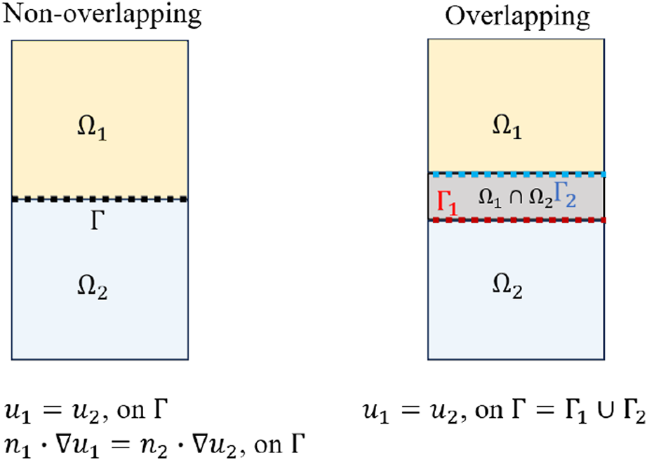
Schematic of non-overlapping and overlapping domain decomposition.
In the overlapping domain decomposition, the two subdomains share an overlap region . The interface of the domain is . It is inside the domain and vice versa. As the interface properly sets boundary conditions for each domain, the convergence of the overlapping domain decomposition only requires data consistency at the interface, i.e., [23]. In conventional numerical methods [23], the overlapping domain decomposition is only applied to spatial domains. However, it should be noted that the two subdomains here can be spatial-temporal subdomains, since there is no particular difference in dealing with temporal and spatial domains in PINNs.
In the context of PINNs, there are two major differences between the non-overlapping and overlapping domain decomposition techniques: (1) the former has no overlapping domains between two adjacent subdomains while the latter does, and (2) both the continuity of the solution and the flux related to the derivative of the solutions are required as the coupling condition at the interface between two adjacent subdomains, while the latter does not explicitly require the continuity of the flux at the interface between two adjacent subdomains, which is able to reduce the cost of the communication in parallel computing.
For each subdomain, a physics-informed neural network (PINN) is assigned as shown in Figure 3. For the subdomain , the total loss consists of the PDE loss , data loss , and interfacial loss , each with their corresponding weights , , and , as defined below:where is the prediction at the interface from the PINN model in the adjacent subdomain. For the forward problem, is the initial/boundary conditions in the subdomain. For the inverse problem, are the measurements on in the subdomain. , and are the number of sample points for their corresponding loss terms. In the present work, we used the same number of PINN models as the number of subdomains, and the PINN model in each subdomain was trained in parallel on different devices using its own loss, i.e., .
FIGURE 3
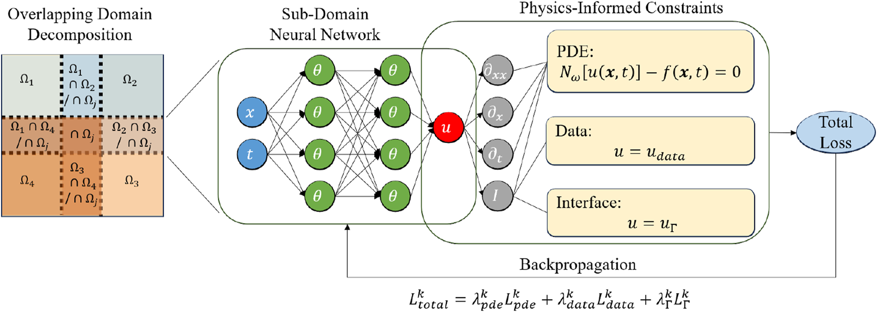
Schematic of a physics-informed neural network with overlapping domain decomposition.
In general, the loss function will be minimised using the stochastic gradient descent approach for both forward and inverse problems. For forward problems, represents the parameters in the neural networks. For inverse problems, denotes the parameters in the neural networks and the parameters used to parameterise . In this approach, we did not require the computation of the first derivative at . In the present approach, each subdomain had a separate PINN model, and the parameters in each PINN model were updated using their own loss, which was defined in Equation 4. To ensure convergence, coupling conditions were imposed on the interface between adjacent subdomains. Furthermore, the adjacent subdomains needed to communicate when computing the loss for the coupling condition. For example, a 1D domain that is divided into three overlapping subdomains should be considered: . Each subdomain had a PINN model and was assigned to a different device (rank 0, 1, or 2 respectively). At the overlapping interface between neighbouring subdomains (e.g., and share ), the PINN predictions at the interface from ranks 0 and 1 were exchanged via a non-blocking send/receive scheme at each gradient descent step. The frequency of communication can be adjusted; however, in this study, we exchanged information between different subdomains at each iteration.
Furthermore, we applied the following rescaling technique to the PINN input in each subdomain as shown in Equation 5:where and can be obtained as we know the boundaries of each subdomain. In this way, the input for PINNs in each subdomain will be rescaled to the range of −1 to 1. For problems with high-frequency solutions, this rescaling will decrease the frequency in each subdomain, and thus migrates the issue of spectral bias in vanilla PINNs.
Results and Discussion
In this section, we present a series of numerical experiments on both forward and inverse PDE problems to demonstrate the accuracy of the overlapping PINNs. Furthermore, we test the speed-up ratio of the overlapping PINNs using an example of an inverse two-dimensional time-dependent heat transfer equation. All the training of PINN models was performed on NVIDIA RTX 3090 GPUs with implementations using the PyTorch 2.3 framework. Details on the computations, e.g., architectures of neural networks, optimisers, etc., for each test case are provided in Supplementary Appendix SA in addition to the first test case.
Forward Problem
1D Forward Problems With High-Frequency Solution
First, we considered the following forward ordinary differential equation (ODE) problems, which are expressed as shown in Equation 6:with the boundary conditions . The exact solution to this equation is given by Equation 7:which is a high-frequency function and is difficult to approximate by DNNs due to the spectral bias [25, 26]. The objective here was to solve Equation 6 given the data on the right-hand side (RHS) and the boundary condition.
To test the accuracy of the overlapping PINNs, we divided the entire spatial domain into four subdomains. Specifically, the subdomains are expressed aswhere . Each subdomain has a length of , and adjacent subdomains overlap by a uniform length of . The interface condition in Equation 4 was applied to ensure continuity of the solution.
The details for the overlapping PINNs are illustrated in Table 1. The points used to calculate the PDE loss within each domain/subdomain were also generated via Latin Hypercube Sampling. The results from the overlapping PINNs are depicted in Figure 4, and they agree well with the reference solution. We also presented the results from the vanilla PINNs and the overlapping PINNs without scaling for the inputs of each subdomain. We observed that: (1) the vanilla and overlapping PINNs without scaling failed to solve this equation accurately due to the spectral bias as reported in [25, 26]; and (2) the overlapping PINNs without scaling were more accurate than the vanilla PINNs for , but the predictions still showed significant discrepancy with the reference solution. For the overlapping PINNs with scaling for the inputs of each subdomain, we were able to decrease the frequency of the target function, which therefore helped mitigate the issue of spectral bias. We used 2,000 uniformly sampled points across the entire domain to estimate the relative errors when training PINN models. The relative errors for the vanilla PINNs, and the overlapping PINNs without and with scaling were found to be , respectively.
TABLE 1
| Settings | Vanilla | Overlapping without scaling | Overlapping with scaling |
|---|---|---|---|
| of layers | 4 | 4 | 4 |
| of neurons per layer | 64 | 64 | 64 |
| Activation fun | Tanh | Tanh | Tanh |
| Optimiser | Adam | Adam | Adam |
| Learning rate | 0.001 | 0.001 | 0.001 |
| Training epoch | 50,000 | 50,000 | 50,000 |
| Collocation points | 200 | 200 | 200 |
| 1 | 1 | 1 | |
| 1 | 10 | 10 | |
| - | 1 | 1 | |
| of GPUs | 1 | 4 | 4 |
ODE problem with a high-frequency solution: Details for the training of PINNs.
FIGURE 4
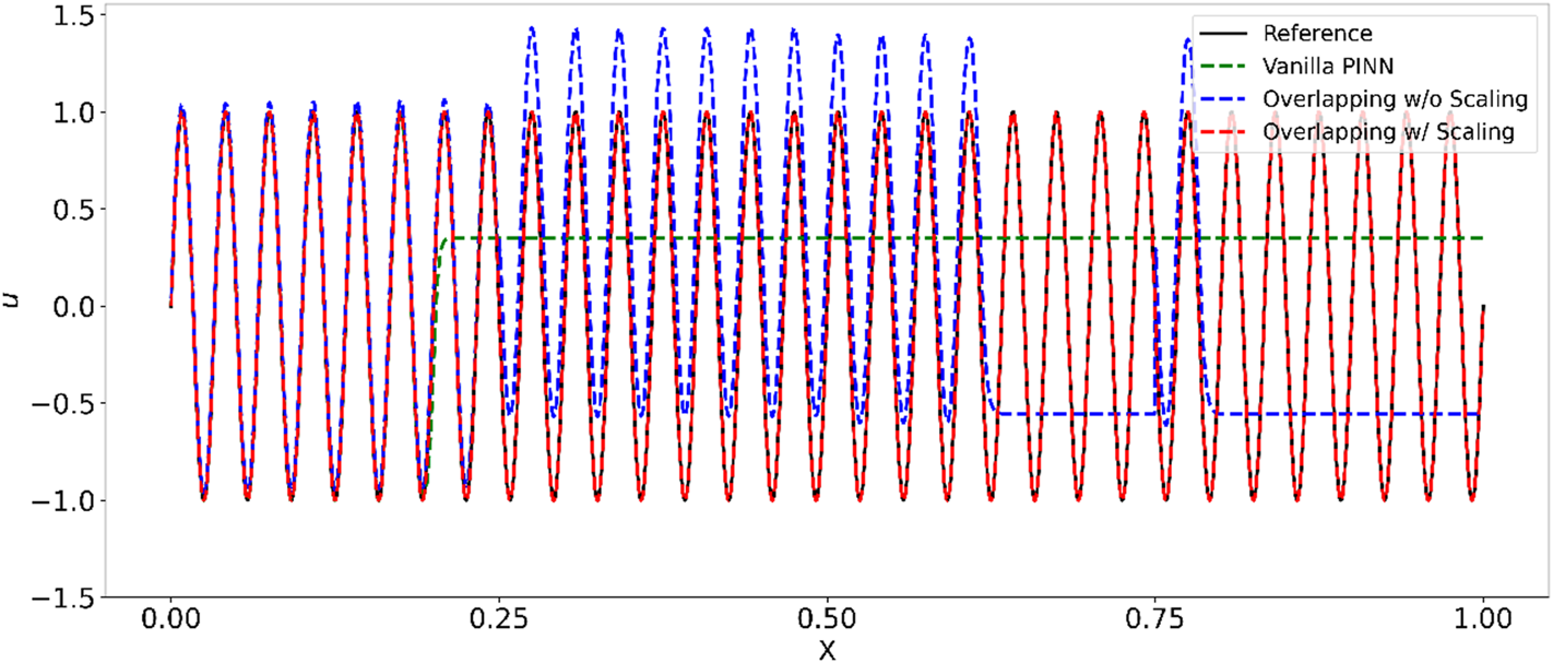
ODE problem with a high-frequency solution: Predictions from vanilla PINNs, overlapping PINNs with and without rescaling of the inputs in each subdomain.
Finally, the loss history of the vanilla PINNs and the overlapping PINNs with and without rescaling is shown in Figure 5. As can be seen the loss for the overlapping PINNs with rescaling decreased the fastest among the three models. In addition, the loss for the overlapping PINNs with rescaling at 20,000 training steps was approximately four orders smaller than the other two models, which is consistent with the results in Figure 5.
FIGURE 5
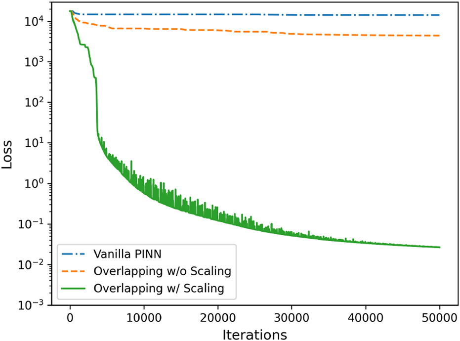
ODE problem with a high-frequency solution: Loss history from vanilla PINNs, overlapping PINNs with and without rescaling of the inputs in each subdomain.
2D Helmholtz Equation
We further tested the spatial parallelism using overlapping PINNs based on the two-dimensional Helmholtz equation, which is a fundamental partial differential equation that arises in various fields such as acoustics, electromagnetics, and quantum mechanics. The equation is expressed as:
The boundary conditions for the equation are specified as shown in Equation 9:where is the Laplacian operator, denotes the boundaries of , and is a constant, which was set as here. The source term is expressed as shown in Equation 10:and we can then obtain the analytical solution to Equation 8 as shown in Equation 11:
Similarly, we divided the entire domain into four subdomains, as shown in Figure 6. The locations for the interfaces that divide the computational domain into four subdomains in the and directions are and , respectively. The details for the overlapping PINN model are listed in Supplementary Table SA1.
FIGURE 6
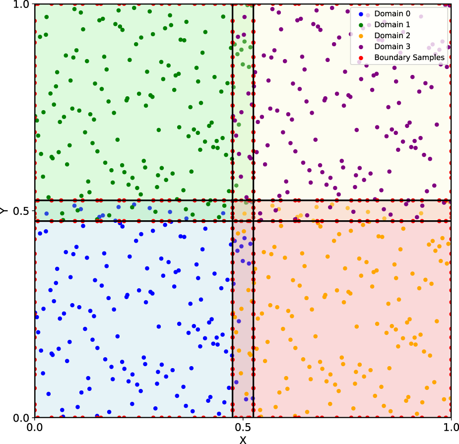
2D Helmholtz equation: Schematic of the domain decomposition. Different subdomains are denoted by different colours.
The results from the overlapping PINNs with four subdomains are shown in Figure 7. It is observed that: (1) the periodic pattern of the solution was well captured by the proposed model (Figure 7a); and (2) the predictions of at two representative locations, i.e., and agreed well with the reference solution as in Figure 7b. In addition, we used the trained PINNs to predict at a uniform grid across the entire domain to estimate the relative errors. The relative error between the predictions from the overlapping PINNs and the reference solution was found to be , demonstrating the good accuracy of the present approach for cases with domain decomposition in the spatial domain.
FIGURE 7
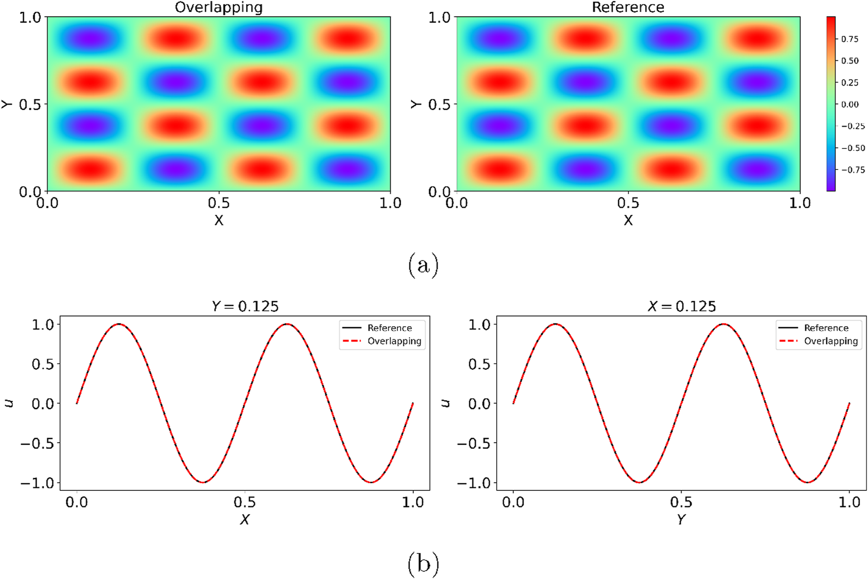
2D Helmholtz equation: Predictions from the overlapping PINNs with four subdomains. Overlapping in (a) and (b): Overlapping PINNs with scaling.
Burgers Equation
We then tested the spatial-temporal parallelism of the overlapping PINNs. The test case considered here is one of the most fundamental partial differential equations in fluid mechanics and nonlinear wave propagation, i.e., Burgers’ equation, which takes the following form as shown in Equation 12:where and are the spatial and temporal coordinates, respectively, is the solution to the equation, and the viscosity coefficient is set to be . The initial condition is given by Equation 13:and the Dirichlet boundary conditions are imposed on the boundaries as specified in Equation 14:
Given the equation and the initial/boundary conditions, we would like to solve this equation with the overlapping PINNs.
Similar to the test case in Section 2D Helmholtz Equation, we divided the entire spatial and temporal domain into four subdomains, as shown in Figure 8. In particular, to demonstrate the flexibility of domain decomposition in the present method, the locations of the interfaces that divide the entire domain into four subdomains in the and directions were calculated as and , respectively. The obtained four subdomains are of two different sizes in the spatial-temporal domains. Coupling conditions were imposed at the interfaces to ensure continuity of the solution. The points that were used to evaluate the losses of the PDE residue and the boundary/coupling conditions were randomly generated. More details are in Supplementary Appendix SA.
FIGURE 8
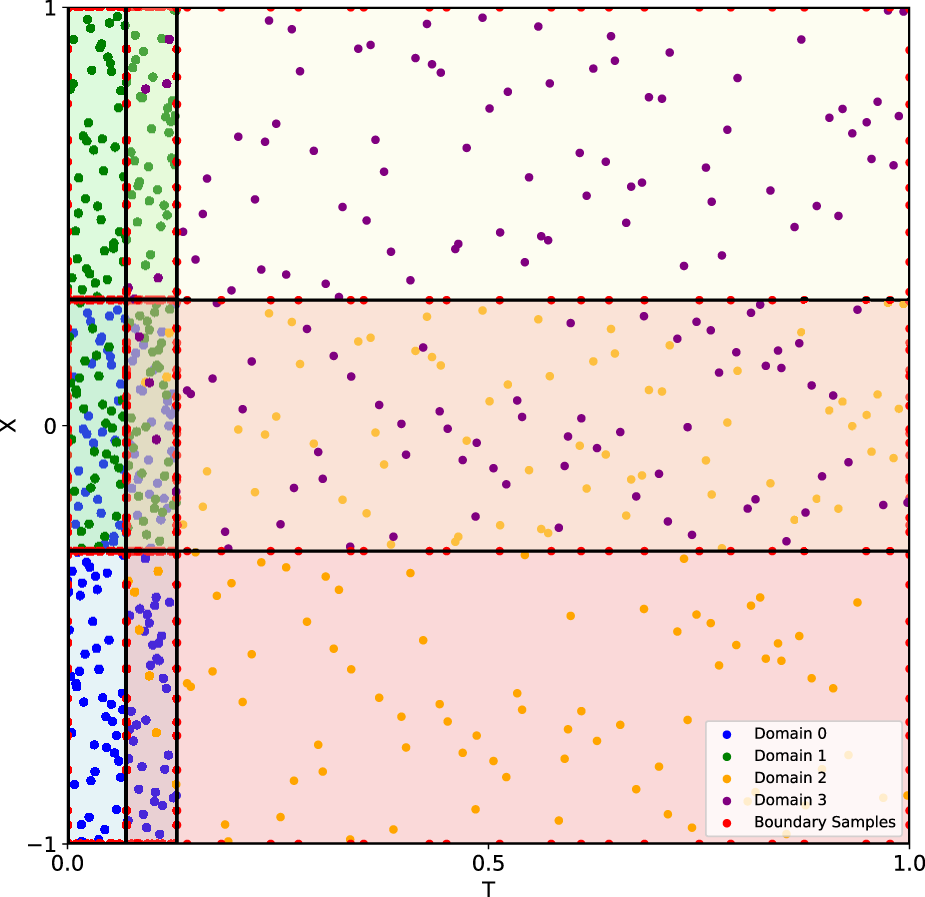
Burgers’ equation: Schematic of domain decomposition. Different subdomains are denoted by different colours.
The predicted from the overlapping PINNs is illustrated in Figure 9. As can be seen the results from the overlapping PINNs showed little discrepancy compared to the reference solution. We further presented the predicted at two representative times, i.e., and 0.7, and the results from the overlapping PINNs agreed well with the reference solution. We used the trained PINNs to predict at a uniform grid to estimate the relative errors. The relative error between the prediction from the overlapping PINNs and the reference solution in the entire spatial-temporal domain was found to be for this particular case, which demonstrates the capability of the present approach for spatial-temporal domain decomposition.
FIGURE 9
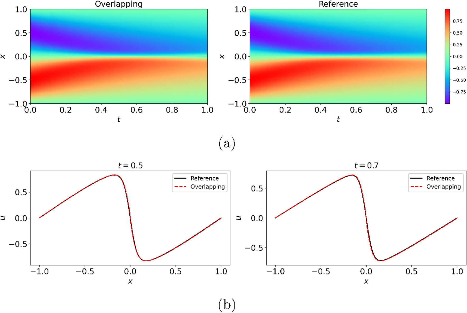
Burgers’ equation: Predictions from the overlapping PINNs with four subdomains in the spatial-temporal domain. Overlapping in (a,b): Overlapping PINNs with rescaling.
Inverse Problem
We then tested the accuracy of the overlapping PINNs for inverse PDE problems. In particular, we tested a steady 2D heat conduction problem in a complex domain and a time-independent heat equation.
2D Heat Conduction
We first tested the overlapping PINNs for spatial parallelism using an example of the heat conduction equation in a complicated domain. As is well known, PINNs are capable of handling problems in complex domains since they represent a mesh-free approach. We demonstrated that the overlapping PINNs are also able to handle problems in complex computational domains effectively. The particular computational domain for the problem considered here is illustrated in Figure 10, which shows a map of Hunan Province, China. The steady heat conduction in this domain is expressed as shown in Equation 15:where is the temperature, is the thermal conductivity, and is the source term. The exact solution for the problem considered here is given by Equation 16:
FIGURE 10
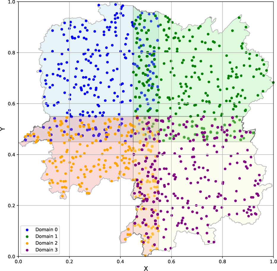
2D Heat conduction: Schematic of the domain decomposition.
In addition, , and the source term can then be derived from the exact solution and .
For the inverse problem considered here, we assumed that measurements of the temperature and the source term were available in the computational domain. Furthermore, the thermal conductivity is an unknown field. The objective was to determine the given the data on and . We tested the accuracy of overlapping PINNs by decomposing the entire domain into four subdomains, as shown in Figure 10. The locations of the interfaces that divide the entire domain into four subdomains in the and directions were found to be and , respectively. The coupling conditions were imposed at the interfaces to ensure continuity of the solution. The points that were used to evaluate the losses of the PDE residue, along with the boundary/coupling conditions were randomly generated. More details are in Supplementary Appendix SA.
The interface conditions and sampling points were generated by the same method used in the Burgers’ equation. The predicted thermal conductivity of the overlapping PINNs is shown in Figure 11. Interestingly, the overlapping PINNs predicted the thermal conductivity well, consistent with the reference solution, even though the domain was irregular. We used 30,000 randomly sampled points in the entire domain to estimate the relative error, and the relative error was found to be 0.026% for the overlapping PINNs. The irregular domain did not impede the PINNs, as the predicted thermal conductivity on the irregular boundaries was smooth. This is an advantage of PINNs compared to the traditional finite element method (FEM), which needs special treatment of irregular computational domains.
FIGURE 11
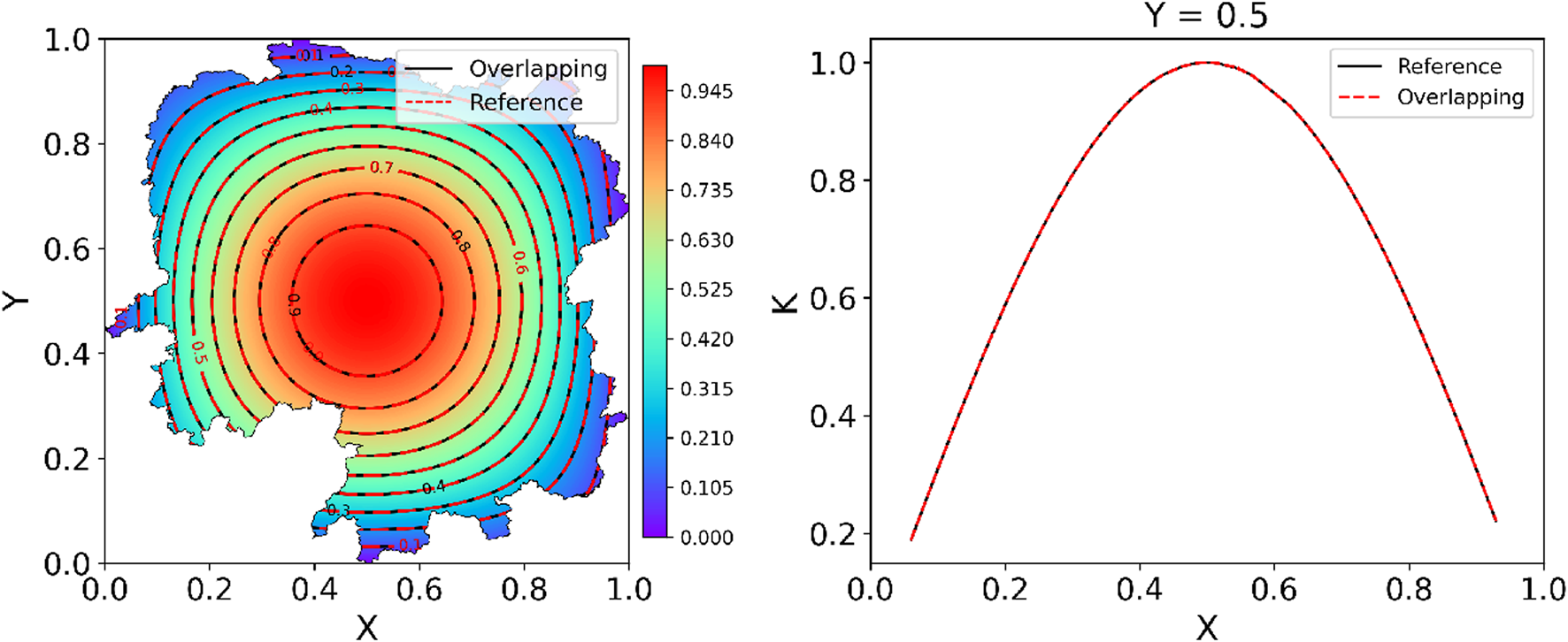
2D Heat Conduction: Predicted from overlapping PINNs with four subdomains. Overlapping: Overlapping PINNs with rescaling.
Time-dependent Heat Transfer Problem
We proceeded to consider a two-dimensional time-dependent heat transfer problem, which is expressed as shown in Equation 17:where is the advection velocity field, is the constant thermal conductivity. In this particular case, the velocity field is defined as shown in Equation 18:The initial condition for the temperature is prescribed as a Gaussian distribution centred at as shown in Equation 19:where is the characteristic length scale controlling the width of the initial distribution, and denotes the initial centre of the field. In this study, , , , and .
According to [27], the exact solution can be obtained as shown in Equation 20 by imposing the the corresponding boundary conditions on the above equation:where , and are the transformed coordinates, which are given by Equations 21, 22:
As in Section 2D Heat Conduction, assuming partial measurements of the temperature field are available, we aimed to infer the thermal conductivity using the overlapping PINNs. Specifically, we decomposed the entire spatial-temporal domain into eight subdomains, as illustrated in Figure 12. The locations of the interfaces that divide the entire domain into several subdomains in the , and directions were , and , respectively. All the points employed to compute the loss of the overlapping PINNs were generated via the Latin Hypercube sampling. Details can be found in Supplementary Appendix SA.
FIGURE 12
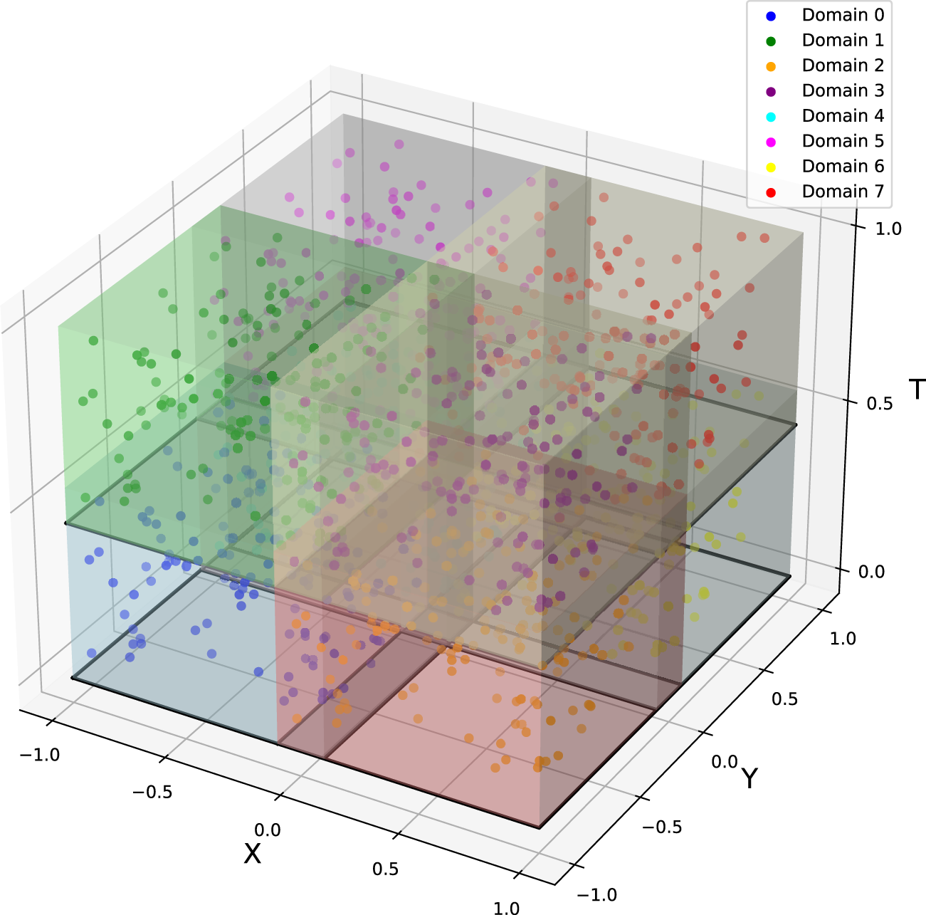
Time-dependent heat transfer problem: Domain decomposition in overlapping PINNs with eight subdomains.
The predicted at three representative times is shown in Figure 13. It should be noted that for all spatial-temporal slices at , , , , and , the overlapping PINNs agreed well with the reference solution. We then employed the trained PINNs to predict on a uniform grid in the entire domain. The relative error, and the relative error between the predictions from the overlapping PINNs and the reference solution were 0.018%. In addition, the predicted was 0.099653, which was quite close to the reference solution .
FIGURE 13
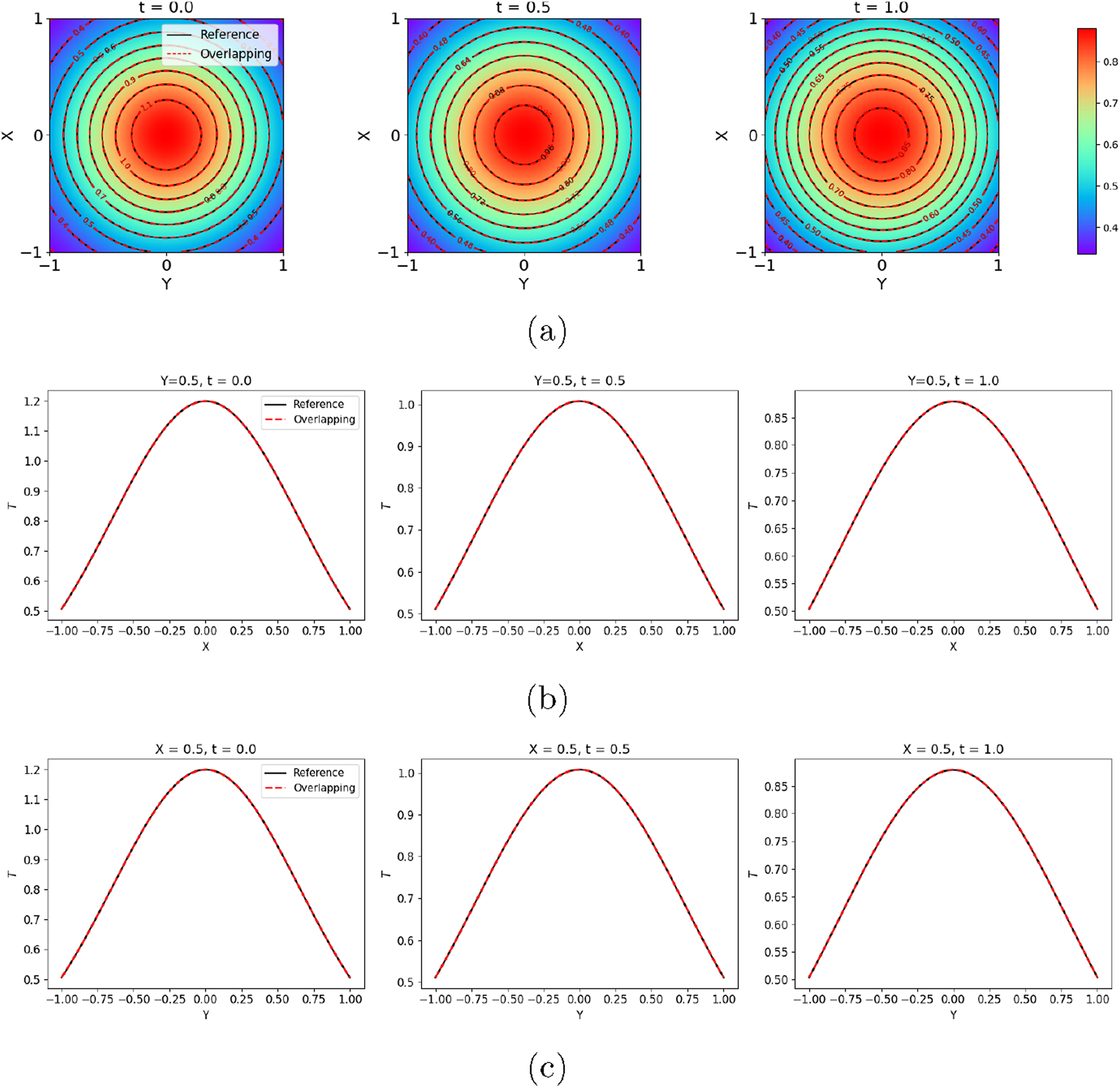
Time-dependent heat transfer problem: Predicted from overlapping PINNs with eight subdomains.: (a) at representative times; (b) and (c) Slices of at different times. Overlapping: Overlapping PINNs with rescaling.
Furthermore, we tested the speed of the overlapping PINNs as we increased the number of subdomains/GPUs. The subdomain division was the same as mentioned above. For the single GPU test, all sample points in the subdomains were assigned to the single GPU. For multiple GPUs, the sample points in the subdomains were evenly assigned to multiple GPUs, meaning each GPU had the same number of sample points. The results of the speed-up ratio (defined as the ratio of the computing time of a single GPU to that of multiple GPUs) of the overlapping PINN are shown in Figure 14. As can be seen, the speed-up ratio increased almost linearly with the number of GPU devices. This demonstrates the effectiveness of parallel computing of the overlapping PINN based on GPUs. For example, when using 8 GPUs, we were able to achieve a speed-up ratio of 7.44, leading to approximately efficiency. The above results demonstrate that the spatial-temporal parallel overlapping PINNs are promising for solving large-scale problems.
FIGURE 14
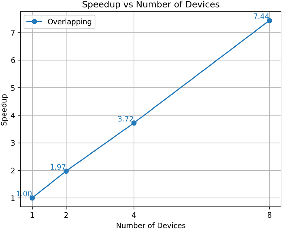
Time-dependent heat transfer problem: Parallel efficiency (Speed-up ratio) of overlapping PINNs with different numbers of subdomains/GPUs.
Summary
In this study, we employed the overlapping domain decomposition approach to enable spatial-temporal parallelism when training PINNs to solve both forward and inverse PDE problems. We proposed a rescaling technique for the inputs of the PINNs in each subdomain to migrate the issue of spectral bias in vanilla PINNs. A wide range of forward and inverse differential equations was used to justify the accuracy of the PINNs with overlapping domain decomposition (overlapping PINNs), including an ODE with high-frequency solution, a steady Helmholtz equation, a heat conduction problem in a complex domain, a time-dependent Burgers’ equation, and heat transfer problems. The results demonstrated that overlapping PINNs were able to achieve high accuracy with both spatial and temporal domain decomposition. Furthermore, in the ODE test problem, we showed that overlapping PINNs with rescaling were able to achieve better accuracy compared to the vanilla PINNs for problems with high-frequency solutions. Additionally, we implemented spatial-temporal parallel PINNs with an overlapping domain decomposition approach using the modern Pytorch distributed package, which enabled distributed training of PINNs on multiple GPUs. The overlapping PINNs achieved approximately efficiency with up to 8 GPUs, as demonstrated by an inverse time-dependent heat transfer problem.
As shown in Sections Burgers Equation and 2D Heat Conduction, the present approach is flexible enough to handle subdomains of different sizes with complex geometry. In general, more residual points are needed in PINNs when solving equations with sharp gradients [12], as compared to equations with smooth solutions. In parallel computing, balancing the computational load among devices is of great importance for achieving good computational efficiency. Due to the flexibility of overlapping PINNs in handling subdomains of different sizes, we can use (1) small subdomains and dense residual points in PINNs at locations where the solutions may have sharp gradients, and (2) larger subdomains but coarse residual points in PINNs for parts that may have smooth solutions. In this way, it is easy to balance the computational cost in different subdomains/devices in order to obtain good parallel efficiency.
One of the most successful applications of PINNs is the flow field reconstruction given partial measurements on the velocity [28] or temperature field [29] from experiments. Currently, the training of PINNs for these real-world applications is time-consuming because (1) a large number of residual points are required in the spatial-temporal domain (three dimensions in space plus one dimension in time) to achieve good accuracy, and (2) the governing equations for fluid dynamics are highly nonlinear, e.g., the Navier–Stokes equations. Considering the great scalability of overlapping PINNs on multiple GPUs, the present framework shows promise in accelerating the training of PINNs for flow field reconstruction. In addition, the present approach can be easily adapted to accelerate the training of PINNs for problems with complex geometries, such as porous media flows [30, 31]. These interesting topics will be addressed in future studies.
Statements
Data availability statement
Data will be made available on reasonable request.
Author contributions
HY: Methodology, Investigation, Coding, Writing - original draft, Visualization. CX: Conceptualization, Methodology, Investigation, Writing - original draft. YZ: Methodology, Investigation, Writing - original draft. XM: Conceptualization, Methodology, Investigation, Coding, Writing - original draft, Supervision, Project administration, Funding acquisition. All authors contributed to the article and approved the submitted version.
Funding
The author(s) declare that financial support was received for the research and/or publication of this article. HY, CX, and XM acknowledge the support of the open fund of the State Key Laboratory of high-performance computing (No. 2023-KJWHPCL-05). XM also acknowledges the support of the Xiaomi Young Talents Program.
Conflict of interest
The authors declare that the research was conducted in the absence of any commercial or financial relationships that could be construed as a potential conflict of interest.
Generative AI statement
The author(s) declare that no Generative AI was used in the creation of this manuscript.
Supplementary material
The Supplementary Material for this article can be found online at: https://www.frontierspartnerships.org/articles/10.3389/arc.2025.14842/full#supplementary-material
References
1.
Raissi M Perdikaris P Karniadakis GE . Physics-Informed Neural Networks: A Deep Learning Framework for Solving Forward and Inverse Problems Involving Nonlinear Partial Differential Equations. J Comput Phys (2019) 378:686–707. 10.1016/j.jcp.2018.10.045
2.
Wang L Liu G Wang G Zhang K . M-pinn: A Mesh-Based PHYSICS-INFORMED Neural Network for Linear Elastic Problems in Solid Mechanics. Int J Numer Methods Eng (2024) 125(9):e7444. 10.1002/nme.7444
3.
Liu X Almekkawy M . Ultrasound Computed Tomography Using Physical-Informed Neural Network. In: 2021 IEEE International Ultrasonics Symposium (IUS). IEEE (2021). p. 1–4.
4.
Yu J Lu L Meng X Em Karniadakis G . Gradient-Enhanced Physics-Informed Neural Networks for Forward and Inverse Pde Problems. Computer Methods Appl Mech Eng (2022) 393:114823. 10.1016/j.cma.2022.114823
5.
Hu Z Shukla K George EK Kawaguchi K . Tackling the Curse of Dimensionality with Physics-Informed Neural Networks. Neural Networks (2024) 176:106369. 10.1016/j.neunet.2024.106369
6.
Cho J Nam S Yang H Yun S-B Hong Y Park E . Separable Pinn: Mitigating the Curse of Dimensionality in Physics-Informed Neural Networks. arXiv preprint arXiv:2211.08761 (2022).
7.
Uddin Z Ganga S Asthana R Ibrahim W . Wavelets Based Physics Informed Neural Networks to Solve Non-Linear Differential Equations. Scientific Rep (2023) 13(1):2882. 10.1038/s41598-023-29806-3
8.
Yin Z Li G-Y Zhang Z Zheng Y Cao Y . Swenet: A Physics-Informed Deep Neural Network (Pinn) for Shear Wave Elastography. IEEE Trans Med Imaging (2023) 43(4):1434–48. 10.1109/tmi.2023.3338178
9.
Kiyani E Shukla K George EK Karttunen M . A Framework Based on Symbolic Regression Coupled with Extended Physics-Informed Neural Networks for Gray-Box Learning of Equations of Motion from Data. Computer Methods Appl Mech Eng (2023) 415:116258. 10.1016/j.cma.2023.116258
10.
Zhang Z Zou Z Kuhl E George EK . Discovering a Reaction–Diffusion Model for Alzheimer’s Disease by Combining Pinns with Symbolic Regression. Computer Methods Appl Mech Eng (2024) 419:116647. 10.1016/j.cma.2023.116647
11.
Cai S Wang Z Wang S Perdikaris P George EK . Physics-Informed Neural Networks for Heat Transfer Problems. J Heat Transfer (2021) 143(6):060801. 10.1115/1.4050542
12.
Mao Z Meng X . Physics-Informed Neural Networks with Residual/Gradient-Based Adaptive Sampling Methods for Solving Partial Differential Equations with Sharp Solutions. Appl Mathematics Mech (2023) 44(7):1069–84. 10.1007/s10483-023-2994-7
13.
Lu L Pestourie R Yao W Wang Z Verdugo F Johnson SG . Physics-Informed Neural Networks with Hard Constraints for Inverse Design. SIAM J Scientific Comput (2021) 43(6):B1105–32. 10.1137/21m1397908
14.
Jeong H Batuwatta-Gamage C Bai J Xie YM Rathnayaka C Zhou Y et al A Complete Physics-Informed Neural Network-Based Framework for Structural Topology Optimization. Computer Methods Appl Mech Eng (2023) 417:116401. 10.1016/j.cma.2023.116401
15.
Paszke A Gross S Chintala S Chanan G Yang E DeVito Z et al Automatic Differentiation in Pytorch (2017).
16.
Ameya DJ Kawaguchi K Em Karniadakis G . Adaptive Activation Functions Accelerate Convergence in Deep and Physics-Informed Neural Networks. J Comput Phys (2020) 404:109136. 10.1016/j.jcp.2019.109136
17.
Shukla K Jagtap AD Karniadakis GE . Parallel Physics-Informed Neural Networks via Domain Decomposition. J Comput Phys (2021) 447:110683. 10.1016/j.jcp.2021.110683
18.
Meng X Li Z Zhang D Ppinn GEK . PPINN: Parareal Physics-Informed Neural Network for Time-Dependent PDEs. Computer Methods Appl Mech Eng (2020) 370:113250. 10.1016/j.cma.2020.113250
19.
Jagtap AD Kharazmi E Em Karniadakis G . Conservative Physics-Informed Neural Networks on Discrete Domains for Conservation Laws: Applications to Forward and Inverse Problems. Computer Methods Appl Mech Eng (2020) 365:113028. 10.1016/j.cma.2020.113028
20.
Jagtap AD Karniadakis GE . Extended Physics-Informed Neural Networks (Xpinns): A Generalized Space-Time Domain Decomposition Based Deep Learning Framework for Nonlinear Partial Differential Equations. Commun Comput Phys (2020) 28(5):2002–41. 10.4208/cicp.oa-2020-0164
21.
De Ryck T Jagtap AD Mishra S . Error Estimates for Physics-Informed Neural Networks Approximating the Navier–Stokes Equations. IMA J Numer Anal (2024) 44(1):83–119. 10.1093/imanum/drac085
22.
Hu Z Jagtap AD Em Karniadakis G Kawaguchi K . When do Extended Physics-Informed Neural Networks (Xpinns) Improve Generalization?arXiv preprint arXiv:2109.09444 (2021).
23.
Dolean V Jolivet P Nataf F . An Introduction to Domain Decomposition Methods: Algorithms, Theory, and Parallel Implementation. SIAM (2015).
24.
Xu S Yan C Zhang G Sun Z Huang R Ju S et al Spatiotemporal Parallel Physics-Informed Neural Networks: A Framework to Solve Inverse Problems in Fluid Mechanics. Phys Fluids (2023) 35(6).
25.
Rahaman N Baratin A Arpit D Draxler F Lin M Hamprecht F et al On the Spectral Bias of Neural Networks. In: International Conference on Machine Learning. PMLR (2019). p. 5301–10.
26.
Xu Z-QJ Zhang Y Luo T . Overview Frequency Principle/Spectral Bias in Deep Learning. Commun Appl Mathematics Comput (2024) 7:827–64. 10.1007/s42967-024-00398-7
27.
Wan X Xiu D George EK . Stochastic Solutions for the Two-Dimensional Advection-Diffusion Equation. SIAM J Scientific Comput (2004) 26(2):578–90.
28.
Cai S Gray C Em Karniadakis G . Physics-Informed Neural Networks Enhanced Particle Tracking Velocimetry: An Example for Turbulent Jet Flow. IEEE Trans Instrumentation Meas (2024) 73:1–9. 10.1109/tim.2024.3398068
29.
Cai S Wang Z Fuest F Jin Jeon Y Gray C Karniadakis GE . Flow over an Espresso Cup: Inferring 3-d Velocity and Pressure Fields from Tomographic Background Oriented Schlieren via physics-informed Neural Networks. J Fluid Mech (2021) 915:A102. 10.1017/jfm.2021.135
30.
Jan Ole Skogestad, KeilegavlenENordbottenJM. Domain Decomposition Strategies for Nonlinear Flow Problems in Porous Media. J Comput Phys (2013) 234:439–51.
31.
George MS Papadrakakis M . Advances on the Domain Decomposition Solution of Large Scale Porous Media Problems. Computer Methods Appl Mech Eng (2009) 198(21-26):1935–45.
Summary
Keywords
parallel PINN, domain decomposition, overlapping, multi-GPU, forward and inverse PDEs
Citation
Ye H, Xu C, Zhou Y and Meng X (2025) Spatial-Temporal, Parallel, Physics-Informed Neural Networks for Solving Forward and Inverse PDE Problems via Overlapping Domain Decomposition. Aerosp. Res. Commun. 3:14842. doi: 10.3389/arc.2025.14842
Received
01 May 2025
Accepted
09 July 2025
Published
18 September 2025
Volume
3 - 2025
Updates
Copyright
© 2025 Ye, Xu, Zhou and Meng.
This is an open-access article distributed under the terms of the Creative Commons Attribution License (CC BY). The use, distribution or reproduction in other forums is permitted, provided the original author(s) and the copyright owner(s) are credited and that the original publication in this journal is cited, in accordance with accepted academic practice. No use, distribution or reproduction is permitted which does not comply with these terms.
*Correspondence: Yuanye Zhou, zhyy2009@163.com; Xuhui Meng, xuhui_meng@hust.edu.cn
Disclaimer
All claims expressed in this article are solely those of the authors and do not necessarily represent those of their affiliated organizations, or those of the publisher, the editors and the reviewers. Any product that may be evaluated in this article or claim that may be made by its manufacturer is not guaranteed or endorsed by the publisher.