Abstract
This study presents a systematic framework for quantifying aerothermal uncertainties in high-pressure turbine nozzle guide vanes (NGV) under combustor-turbine interaction, focusing on the combined impacts of hot streak spatial variations and turbulence intensity fluctuations. By integrating parametric modeling of combustor-exit temperature fields, non-intrusive polynomial chaos expansion (PCE), and Sobol sensitivity analysis, the methodology enables probabilistic evaluation of aerothermal performance across arbitrary turbine locations. Conjugate heat transfer simulations were conducted to analyze the effect of stochastic parameters on the NGV metal temperature uncertainty. The findings reveal that cooled NGVs exhibit an 80% increase in mean total pressure loss and 42% higher fluctuation amplitudes, driven by enhanced midspan mixing and counter-rotating vortices. Localized metal temperature fluctuations reach 4.3% of inlet total temperature, concentrated in cooling transition zones and secondary flow paths. Turbulence intensity dominates uncertainty contributions, while hot streak circumferential variations show minimal influence. The PCE based framework, augmented by Hammersley sampling, achieves computational efficiency with 20 samples, demonstrating robust capability for cooling system design under realistic inflow uncertainties. This work advances probabilistic aerothermal analysis methodologies, offering critical insights for turbine architectures operating under lean-burn combustor conditions.
Introduction
As a critical hot-end component in aero-engines, the high-pressure turbine (HPT) operates under extreme thermal-mechanical conditions characterized by high temperatures, elevated pressures, and complex flow and thermal interactions. These harsh operational environments present significant cooling challenges while simultaneously rendering the turbine susceptible to ablation. Although turbine cooling technologies have evolved considerably over decades, the conventional approach of increasing coolant mass flow rates demonstrates diminishing returns in cooling effectiveness. Furthermore, insufficient understanding of combustor outflow characteristics has necessitated overconservative safety margins for cooling systems originally designed under idealized uniform inflow assumptions, resulting in excessive coolant consumption and associated engine performance penalties [1]. Consequently, contemporary research priorities have shifted toward three synergistic domains: combustor-turbine interaction effects and operational environment impacts, advanced cooling configurations combined with innovative manufacturing techniques, and systematic uncertainty quantification methodologies [2].
The high-pressure turbine faces intensified cooling design challenges under evolving combustor technologies. The widespread adoption of Rich-Quench-Lean (RQL) combustion and lean premixed systems, while effectively reducing NOx emissions and ensuring combustion stability, induces pronounced non-uniform parameters at the combustor-turbine interface. These manifest as temperature distributions, intense swirling flows, and elevated turbulence intensity, collectively introducing substantial uncertainties in the turbine inlet conditions regarding temperature and velocity fields. Such uncertainties complicate the optimization of cooling system under fixed coolant flow constraints [3, 4]. The root causes of these operational uncertainties stem from spatial variations in temperature fields, swirl patterns, total pressure distributions, and turbulence intensities, specifically involving the circumferential/radial position of hot streak cores, swirl structure non-uniformity, and turbulence magnitude fluctuations. Feng et al. [5] demonstrated that combustor-exit temperature non-uniformities, particularly the hot streaks, exacerbate flow complexity and thermal uncertainty within turbine passages. This phenomenon elevates risks of localized blade overheating and potential ablation, ultimately compromising turbine reliability and operational lifespan. Notably, distinct radial temperature profiles with identical mean values exert divergent impacts on durability, as evidenced by comparative studies [6]. Numerical investigations by Feng et al. [7] on 1.5-stage high-pressure turbine configurations revealed that it is an effective way to reduce the heat load and improve the adiabatic efficiency by reasonably matching the hot streak and the stator clocking positions. Furthermore, the aerothermal uncertainty in high-pressure turbine is also linked to turbulence intensity. Combustor exit turbulence, inherently unsteady and challenging to measure experimentally, exhibits significant operational impacts. Ames et al. [8] computationally quantified turbulence intensities approaching 19% in this region, demonstrating their profound influence on heat transfer augmentation and blade life. Krishnamoorthy et al. [9] established through empirical correlations that localized turbulence levels of 12% amplify heat exchange rates by 75% compared to laminar conditions. Consolidated research findings [8–10] confirm that turbulence-driven boundary layer transition mechanisms precipitate substantial heat transfer rate escalation. Wang et al. [11] systematically compared heat transfer characteristics under varying turbulence intensities and hot streak circumferential positions, revealing that turbulence enhancement improves blade surface temperature uniformity while accelerating hot streak dissipation within stator passages.
Traditional research predominantly operates under deterministic parameter assumptions, yet the inherent non-uniformity and unsteadiness of thermal and fluid fields at combustor-turbine interfaces fundamentally limit such approaches. Deterministic numerical studies inherently fail to isolate the causal relationships between inflow uncertainties and aerothermal responses in high-pressure turbines. Recent advances in uncertainty quantification (UQ) methods have enabled systematic evaluations of manufacturing variations (e.g., film cooling hole tolerances), assembly deviations (e.g., blade tip clearance variations), and inflow parameter fluctuations [12–15]. However, limited attention has been directed toward UQ analyses addressing combustor-turbine interaction induced non-uniform thermo-fluid uncertainties. Montomoli et al. [16] pioneered UQ applications in this area by assessing three critical parameters (hot streak circumferential position, turbulence intensity, and thermal barrier coating thickness) on nozzle guide vane (NGV) midspan metal temperatures. Their sensitivity analysis identified hot streak circumferential location as the dominant factor influencing temperature distributions, though the study’s scope excluded critical considerations of hot streak physical scales and radial position. Schneider et al. [17, 18] developed complementary experimental and numerical frameworks combining parametric modeling with UQ techniques to investigate residual swirl and hot streak characteristic uncertainties in lean-burn combustor environments. While their work established methodology benchmarks, detailed quantification results for individual stochastic parameters remain unreported, particularly regarding the interaction mechanisms between swirl and unsteady heat transfer phenomena.
Existing research remains limited in comprehensively quantifying the impacts of inflow temperature and flow field uncertainties on high-pressure turbine aerothermal characteristics, with most uncertainty quantification studies focusing on localized regions such as midspan sections, blade tips, and endwall rather than providing holistic assessments of turbine blade performance. To address this knowledge gap, this study develops an integrated combustor-turbine interaction uncertainty quantification system through hybrid script integration of MATLAB, Python, and ANSYS CFX. The system synergizes parameterized models of high swirl combustor exit temperature and flow fields with non-intrusive polynomial chaos expansion methods, enabling probabilistic analysis across arbitrary turbine locations. Through conjugate heat transfer simulations, the effects of combustor exit hot streak circumferential and radial position uncertainties and turbulence intensity variations on NGV performance have been systematically investigated. Sobol sensitivity indices quantitatively evaluate each parameter’s contribution to aerothermal response variances. This methodological framework provides critical insights for reliability-driven design optimization of high-pressure turbine under realistic combustor-turbine coupling conditions.
Numerical Methods
This study employs the commercial CFD solver ANSYS CFX for steady conjugate heat transfer analysis using unstructured meshes. Within the framework of fluid mechanics theory, the fundamental governing equations for fluid motion encompass the conservation laws of mass, momentum, and energy. In Cartesian coordinates, the differential form of this system is expressed as follows:
Mass conservation equation as Formula 1:
Momentum conservation equation as Formula 2:
Energy conservation equation as Formula 3:where τ denotes the shear stress tensor, SM represents the momentum source term, SE is the energy source term, quantifies viscous dissipation work, signifies work by external momentum sources, htot designates total enthalpy, and δ the Kronecker delta function.
Conjugate heat transfer simulations necessitate solving the solid-domain energy conservation equation as shown in Formula 4:
The finite volume method governs the spatial discretization of the governing equations, with numerical solutions obtained through a high resolution second order central differencing scheme. The total energy formulation models temperature evolution throughout the flow domain, incorporating viscous dissipation effects. Conservative interface heat flux conditions rigorously enforce energy conservation at fluid-solid boundary. Subsequent sections provide detailed descriptions of the computational framework, including turbulence model validation, boundary condition implementation, and comprehensive grid independence verification procedures.
Computational Model and Boundary Conditions
The investigation focuses on a geometrically representative, the NGV from the first stage of a high-pressure turbine, comprising 40 vanes with an axial chord length of 66 mm. The airfoil geometry features leading and trailing edge heights of 62 mm and 50 mm respectively, incorporating internal cooling chambers divided into forward and aft cavities with cooling air supplied through lower and upper inlets. Nineteen film cooling rows are distributed across the NGV surface. Geometrical simplifications have been implemented at secondary regions, that is the endwall film holes and trailing edge cutback features have been eliminated to reduce computational complexity, as illustrated in Figures 1a,b. The computational domain employs a periodic two-vane sector configuration with 18° circumferential span, maintaining a 2:1 vane-to-swirler count ratio to preserve flow periodicity. This computational framework integrates the fluid domain with simplified metallic NGV, incorporating a contoured hub profile matching combustor exit flowpath dimensions. Temperature-dependent thermophysical properties are implemented through user-defined real gas formulations for the working fluid, while the nickel-based superalloy substrate adopts a constant thermal conductivity of λ = 19.2 W/(m·K) based on reference material data.
FIGURE 1
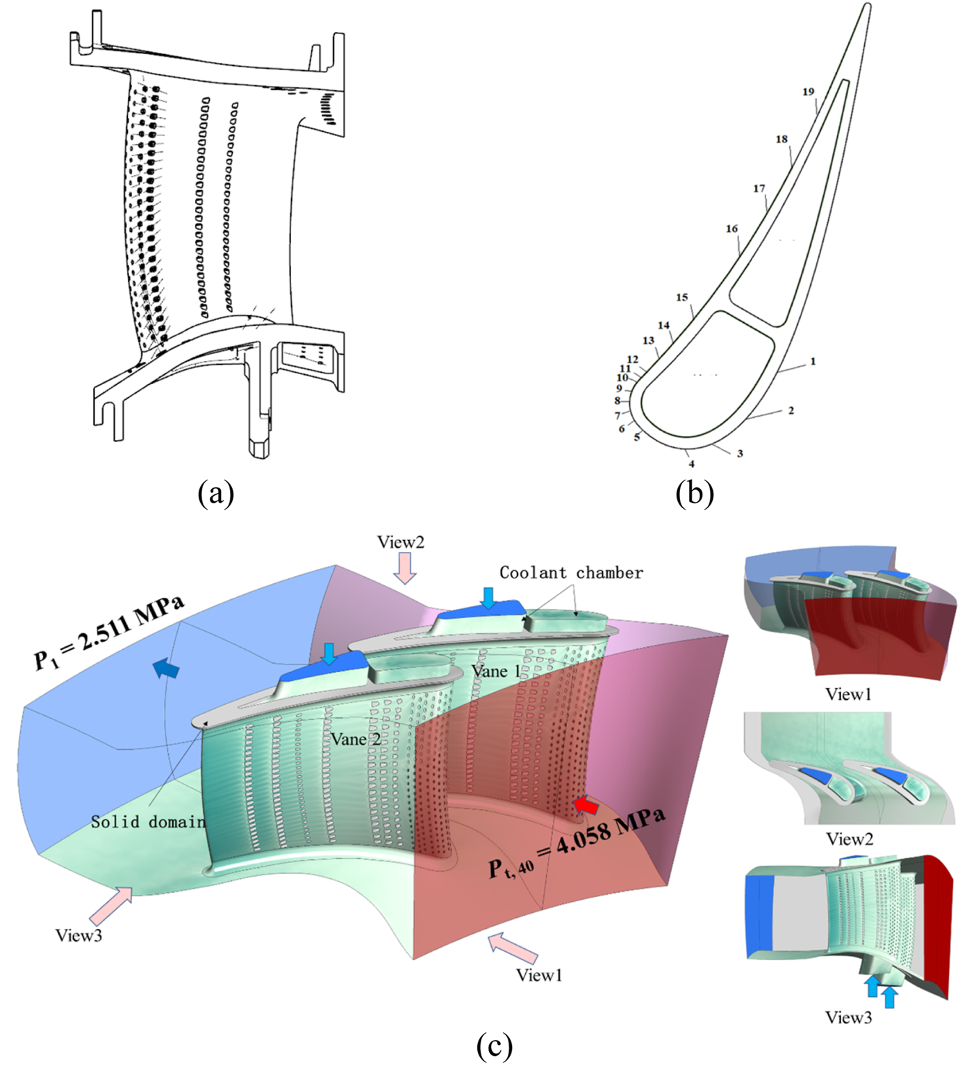
Schematic views of NGVs and computational domain. (a) Meridional cascade channel. (b) Cooling hole row arrangement. (c) Computational domain.
The computational domain configuration is illustrated in Figure 1c, with prescribed inlet boundary conditions comprising uniform total pressure, non-uniform turbulence intensity, and non-uniform total temperature profiles. The temperature non-uniformity derives from randomly sampled temperature distributions generated through parametric modeling, while turbulence intensity magnitudes undergo concurrent stochastic variations. Detailed methodological implementations are elaborated in subsequent section. The outlet enforces uniform static pressure conditions. Coolant supplies to forward and aft cavities are governed by mass flow rate and total temperature specifications. Rotational periodicity boundaries are imposed on lateral fluid domain surfaces, with conservative interface heat flux conditions applied at all fluid-solid interfaces. Remaining walls are designated as adiabatic surfaces. Comprehensive boundary condition specifications are tabulated in Table 1.
TABLE 1
| Parameter | Value |
|---|---|
| Inlet total pressure, Pt | 4.058 MPa |
| Inlet total temperature, Tt | random sample |
| Main stream turbulence intensity, TI | random sample |
| Outlet static pressure, P | 2.511 MPa |
| coolant mass flow rate in front chamber, Mc1 | 161.02 g/s |
| coolant mass flow rate in back chamber, Mc2 | 51.66 g/s |
| Coolant total temperature, Tt, c | 956.4 K |
| Coolant turbulence intensity, TIc | 5% |
Boundary conditions.
Parameterized Model of Combustor Outlet Temperature Field
Given the practical challenges in acquiring authentic combustor exit thermal and fluid distributions from operational engines, this study adopts the non-reacting lean-burn combustor simulator developed by Zhang et al. [19], as illustrated in Figure 2. The swirler configuration employs a negative-swirling (NSW) operational mode with direct alignment to the NGV flow passages. To properly capture combustor-turbine interaction effects, the original turbine section has been replaced with the uncooled nozzle guide vane passage investigated in this study. Unsteady numerical simulations following the methodology described in the reference were conducted to obtain the required two-dimensional time-averaged hot streak temperature fields at the combustor-turbine interface (designated as Plane40 in subsequent analysis).
FIGURE 2
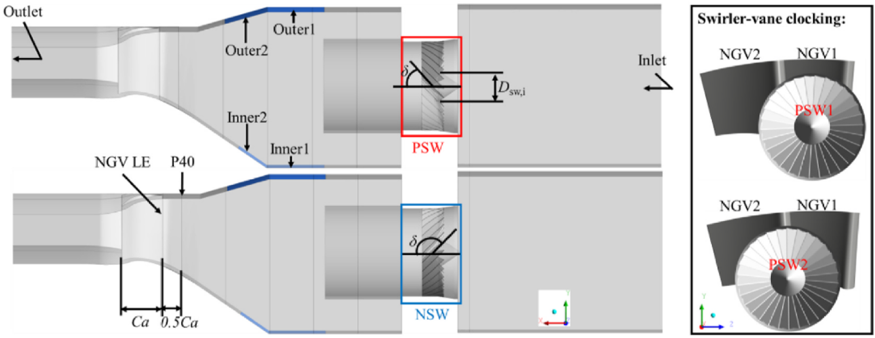
Schematic view of the full geometry including the combustor and NGVs [19].
The parametric modeling process for combustor exit temperature fields is illustrated in Figure 3, employing dimensionless temperature, where Tt denotes local total temperature and Tref represents the reference value derived from Plane40’s average total temperature. The overall inputs and outputs of parametric modeling are shown in Figure 3a. The methodology proceeds as follows: initial unsteady numerical simulations under boundary conditions specified in Figure 3b yield the target time-averaged temperature field at Plane40, which is decomposed into hot streak structures superimposed on a radial baseline distribution. High temperature cores are identified through the criterion Tt/Tref >1, with residual regions constituting the baseline field. MATLAB-based parametric modeling treats hot streak and baseline components as additive contributions at each spatial location. Hot streak positioning is parameterized through circumferential offset Δθhs and radial displacement Δrhs that are relative to the channel center (θ0, r0), maintaining fixed relative positioning between left/right hot streak as depicted in Figure 3c. The resultant hot streak center coordinates become (θ0+Δθhs, r0+Δrhs).
FIGURE 3
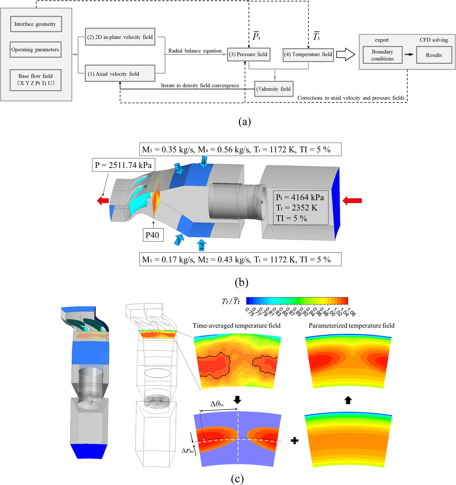
Modeling of total temperature field at combustor exit. (a) Parametric modeling flowchart. (b) Combustor simulator boundary conditions. (c) Basic flow of time-averaged temperature field parameterization.
Turbulence Model Validation
The selection of appropriate turbulence models proves critical for accurate blade heat transfer predictions due to the strong sensitivity of RANS simulation outcomes to turbulence model selection. Our research group previously conducted comprehensive turbulence model validation using NASA’s fully film-cooled C3X vane [20] in prior investigations [21, 22], as depicted in Figure 4. This benchmark configuration features a Z-shaped adiabatic splitter dividing the airfoil into two sections, incorporating three internal cooling cavities, nine film cooling hole rows, and ten vertical coolant channels. Detailed geometric parameters and mainstream flow conditions are documented in reference [20].
FIGURE 4
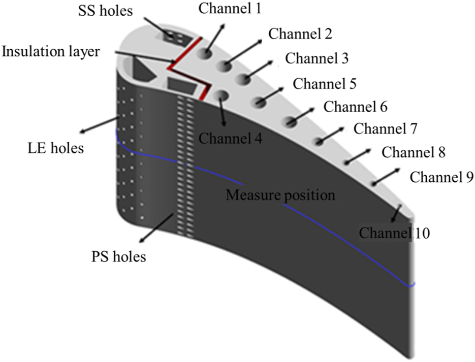
The geometry model of full film cooled C3X vane [20].
Case 34145 of C3X from Wang et al. [21] was selected for conjugate heat transfer analysis, comparing five turbulence models’ predictions against experimental data for wall temperature and heat transfer coefficient (HTC) distributions. As shown in Figure 5, both SST k-ω and SST k-ω+γ-θ models demonstrated satisfactory agreement with test measurements across most regions. The SST k-ω+γ-θ model exhibited maximum temperature deviations of 3.7%–6.5% from experimental values, with HTC prediction errors reaching 17% on the pressure surface. Significant discrepancies emerged among the five models’ predictions for leading edge thermal parameters in the absence of experimental data. Wang et al. [11] demonstrated the superior capability of SST k-ω+γ-θ in capturing leading edge heat transfer and suction side transition characteristics for uncooled C3X configurations compared to alternative turbulence models. Further validation studies by Charbonnier et al. [23] and Jiang et al. [24] on film-cooled vanes confirmed the enhanced predictive accuracy of SST k-ω+γ-θ implementation for leading edge thermal analyses relative to standard SST model. Based on this consolidated validation evidence, the SST k-ω+γ-θ model was adopted for the present numerical study.
FIGURE 5
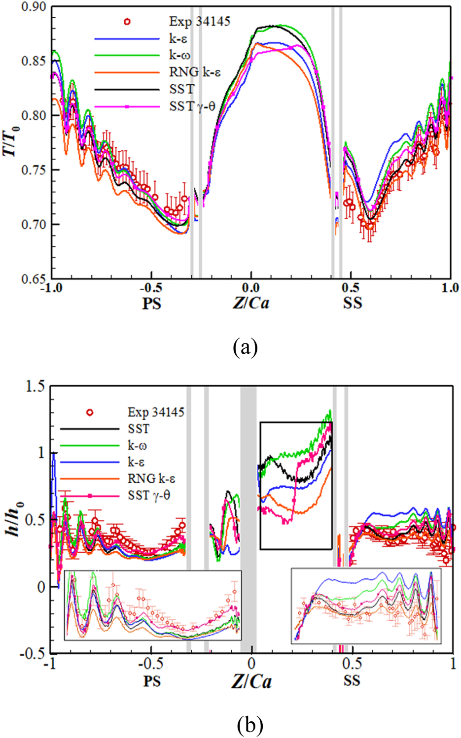
Temperature and HTC on film cooled C3X vane surface [21]. (a) Wall temperature distribution, T0 = 703 K. (b) HTC distribution, h0 = 1135 W/(m2·K).
Grid Independence Verification
This study employs ANSYS Mesh for unstructured grid generation, utilizing the SST k-ω+γ-θ turbulence model. The near-wall mesh resolution of 7 × 10⁻⁴ mm ensures boundary layer resolution with y+ values maintained below 5 throughout wall-adjacent regions, as demonstrated in Figure 6. The achieved average y+ of 1.8 satisfies the turbulence model’s near-wall treatment requirements.
FIGURE 6
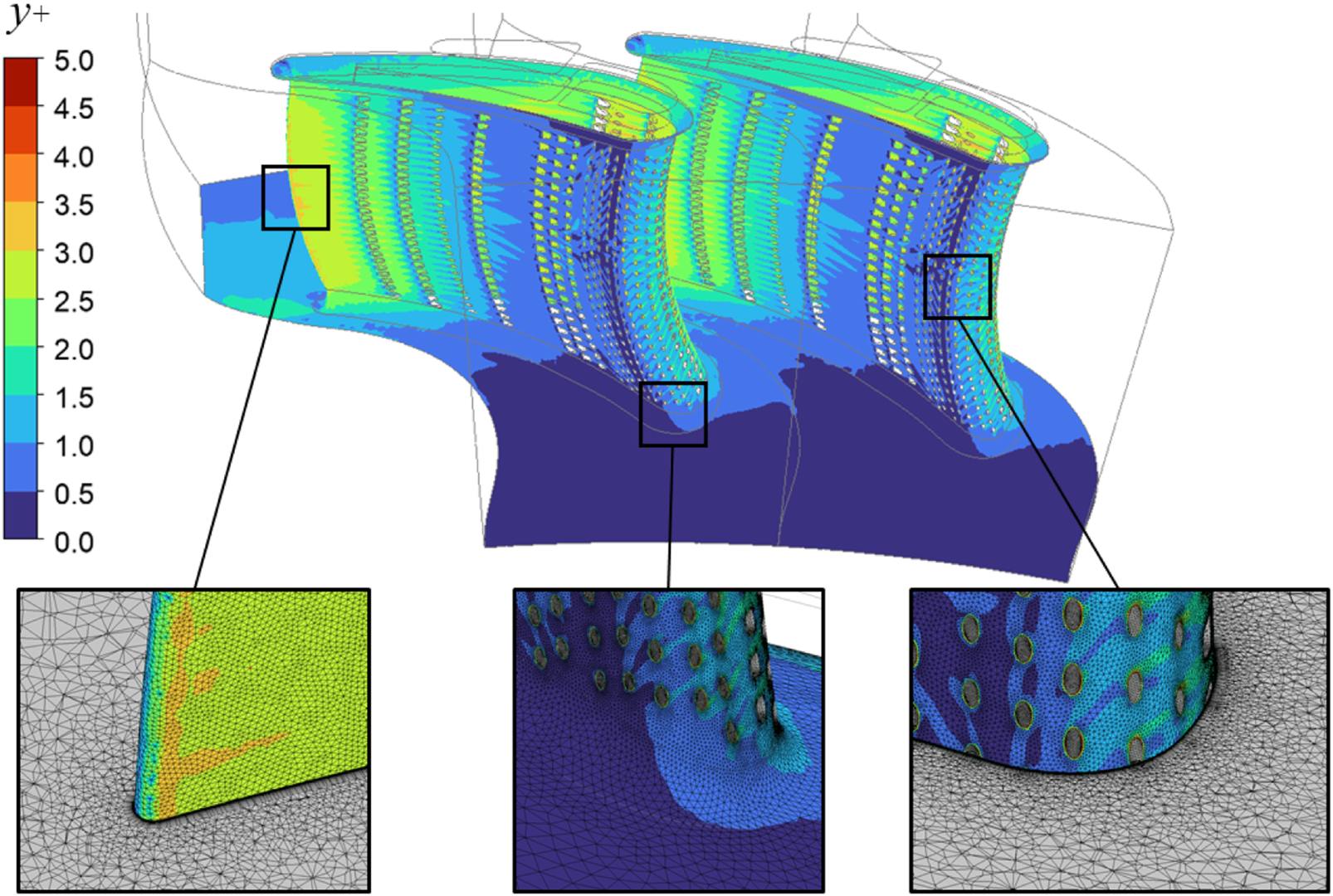
Distribution of non-dimensional wall distance y+ with details of mesh.
Steady simulations under prescribed inlet temperature distributions and 15% turbulence intensity were conducted across four grid resolutions to establish solution independence: dual-vane passage meshes containing 25.6 million, 42.0 million, 67.28 million, and 109.16 million elements respectively. Convergence was monitored through temperature profiles downstream of cooling holes and mass flow rate imbalances between mainstream and coolant paths, with residual levels sustained below 1 × 10⁻⁵ and parameter imbalances remaining under 0.02% during iterative stabilization. Figure 7 presents midspan temperature distributions across all mesh configurations, while Table 2 quantifies corresponding vane surface average temperatures versus nodal counts.
FIGURE 7
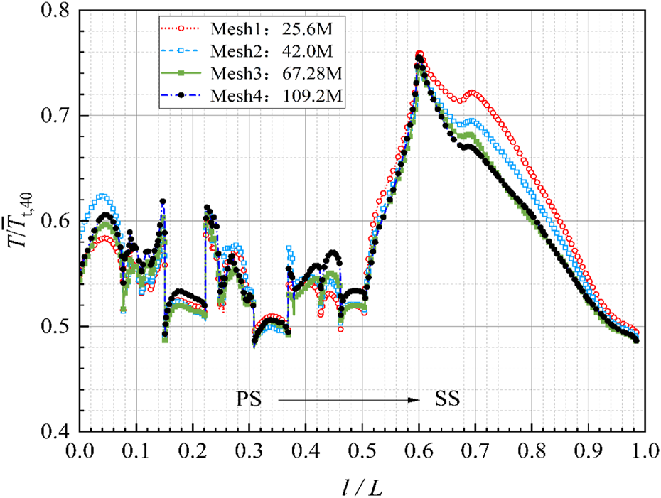
Distribution of midspan temperature.
TABLE 2
| Mesh | Elements/million | Average temperature/K | Deviation/% |
|---|---|---|---|
| Mesh 1 | 25.60 | 1,133.82 | 2.569 |
| Mesh 2 | 42.00 | 1,123.53 | 1.638 |
| Mesh 3 | 67.28 | 1,106.63 | 0.109 |
| Mesh 4 | 109.16 | 1,105.42 | - |
The mesh elements number and average temperature on the two vanes.
Comparative analysis reveals a mere 0.109% deviation in surface-averaged temperature between Mesh3 and the finest mesh Mesh4, demonstrating pronounced grid independence beyond 67.28 million elements. The negligible temperature variation (0.109%) between Mesh3 and Mesh4 confirms further mesh refinement exerts negligible influence on solution accuracy. Considering computational resource constraints inherent to the study’s parametric scope, Grid 3 with 67.28 million elements was selected for subsequent analyses. Detailed mesh topology characteristics are also illustrated in Figure 6.
Uncertainty Quantification Methods
This study addresses computational fluid dynamics (CFD) applications in engineering through deterministic modeling of computational domains with prescribed boundary conditions, where numerical solvers generate output responses. For well-posed problems, the n-dimensional vector X can be used to represent the set of single multiple random inputs [x1, x2, …, xn], such as temperature, flow rate, pressure. The vector Y can represent the various outputs [y1, y2, …, ym] obtained, such as the efficiency and temperature distribution. And the correspondence can be summarized as Formula 5:where f denotes the mapping of inputs to outputs, and in numerical simulation f is a single. When considering uncertainty quantification (UQ), stochastic input parameters are represented by random vector I = [X1, X2, …, Xn] with prescribed probability distributions, propagating through the computational model to yield uncertain outputs as shown in Formula 6:
The polynomial chaos expansion (PCE) method, originally developed by Wiener [25] using Hermite polynomials for normal-distributed inputs and later generalized by Xiu et al. [26] for arbitrary distributions, provides an efficient framework for such analyses. Traditional Monte Carlo (MC) method requires 10n+2 simulations to achieve 10−n confidence levels in output statistics [27], becoming computationally prohibitive for complex models. In contrast, PCE achieves comparable accuracy to MC with orders-of-magnitude fewer samples by constructing surrogate models through orthogonal polynomial basis functions [12]. Consequently, while MC remains applicable for post-processing surrogate model statistics, this study adopts PCE as the principal UQ methodology.
Polynomial Chaos Expansion
The polynomial chaos expansion (PCE) methodology comprises intrusive and non-intrusive formulations. Intrusive implementations require solver code modifications, rendering them primarily applicable to simplified numerical frameworks. Non-intrusive PCE decomposes input-output relationships into deterministic and stochastic components through infinite series expansions [28, 29] as Formula 7:where n denotes the number of random variables, a represent undetermined coefficients resolved through sampling, Ψk symbolize chaos polynomials, and ξ = (ξi1, ξi2, …, ξin) constitutes the random variable vector. Practical implementations employ finite truncation at polynomial order p, typically governed by Formula 8:
Then the number of coefficients to be determined for the required solution can be calculated by Formula 9:
A second order polynomial expansion (p = 2) provides an optimal balance between solution accuracy and numerical stability [17]. Polynomial basis selection adheres to the Wiener-Askey scheme [26], which prescribes orthogonal polynomial families aligned with random variable probability distributions. For instance, Hermite polynomials for Gaussian distributed variables.
The determination of undetermined coefficients in polynomial chaos expansions primarily employs quadrature-based projection and collocation methods [17]. The quadrature approach utilizes numerical integration through quadrature points to compute projection integrals, demonstrating high efficiency for low-dimensional problems. However, its computational cost escalates exponentially with increasing random variables due to the curse of dimensionality. In contrast, the collocation method treats the solver as a black-box, sampling the probabilistic input space to construct response surfaces. While ensuring exact solutions at collocation points, this method lacks inherent error control elsewhere. To enhance accuracy and mitigate numerical errors, an oversampling factor k multiplies the minimum required samples. Hosder et al. [30] recommend k = 2, forming an overdetermined system through Formula 10:
Though exhibiting slower convergence rates, collocation method proves advantageous for high-dimensional problems. This study adopts the collocation approach with second-order polynomial expansions (p = 2) and Hammersley sampling for non-intrusive PCE implementation.
Building upon Section Parameterized Model of Combustor Outlet Temperature Field’s parameterization framework, the baseline temperature field derives from time-averaged unsteady simulations at combustor-turbine interface Plane40. Stochastic perturbations are introduced through hot streak circumferential and radial position uncertainties, coupled with turbulence intensity variations. Then the number of sample points required is 20 according to the Formula 10. Following UQ conventions [16, 17] and acknowledging absent probabilistic data, all variables assume normal distributions with baseline values as average. Table 3 details their probabilistic configurations.
TABLE 3
| Parameter | μ | σ |
|---|---|---|
| Hot streak circumferential position θ/° | 98 | 1.5 |
| Hot streak radial position r/mm | 360.724 | 5 (10% span) |
| turbulence intensity TI/% | 15 | 3 |
Probability distribution of random variables.
Sobol Indice Sensitivity Analysis
This study employs Sobol sensitivity indices to quantify the relative contributions of input parameter uncertainties to output response variances, utilizing a variance-based global sensitivity analysis framework. Upon determining the polynomial chaos expansion coefficients, the expectation and variance of output responses can be expressed as Formulas 11, 12:
Following Sudret [31] and Crestaux et al. [32] and Schaefer et al. [33], the total variance decomposes into Formula 13:where the partial variance components are defined as Formula 14:
The Sobol index is formulated as the ratio of partial variance to total variance as shown in Formula 15:
The total contribution of an input variable to output uncertainty aggregates all Sobol indices involving that parameter. For instance, with three input variables (i = 3), the total contribution of the first variable comprises can be calculated in Formula 16:
Framework of Uncertainty Quantification Methods
This study establishes an integrated aerothermal uncertainty quantification system for turbine NGV under combustor-turbine interaction, as illustrated in Figure 8. The framework synergizes non-intrusive polynomial chaos expansion methodology with ANSYS CFX simulations, incorporating a parameterized inlet temperature field model. Implementation employs Hammersley sampling and collocation methods through Python-driven coefficient determination to construct surrogate models, augmented by Sobol sensitivity analysis for uncertainty decomposition.
FIGURE 8
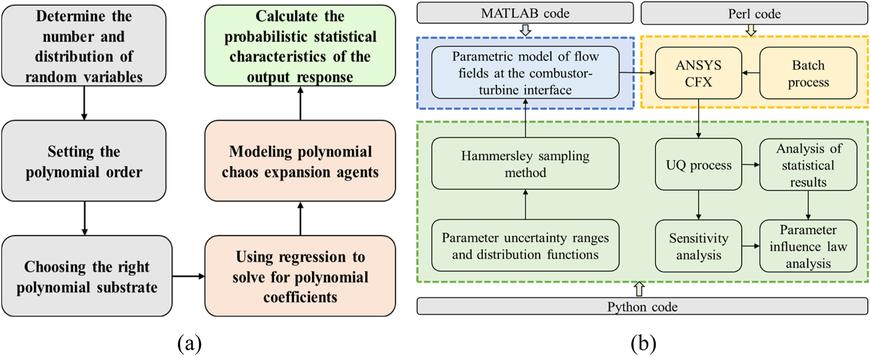
Uncertainty quantification system framework for the aerothermal characteristics of turbine vanes. (a) Polynomial chaos expansion method. (b) Uncertainty quantification process.
The developed system enables comprehensive evaluation of three stochastic inlet parameters, including hot streak circumferential position, radial position, and turbulence intensity, on high-pressure turbine vane aerothermal performance. Subsequent analyses quantify mean values, standard deviations, and correlation coefficients for adiabatic film cooling effectiveness and metal temperature distributions. Sobol indices elucidate thermal load sensitivity variations across critical regions including leading edge and pressure side. Comparative assessments further differentiate parameter influence mechanisms between lean-burn and conventional rich-burn combustor configurations with distinct hot streak scaling characteristics.
Results and Discussions
Uncertainty in Aerodynamic Performance
To quantify the uncertainty of flow losses within cooled NGV passages under stochastic variations of hot streak and turbulence intensity, a total pressure loss coefficient analogous to that of uncooled NGV is employed. Figure 9 illustrates the uncertainty characterization of the cooled vane exit total pressure loss coefficient derived through quantification procedures, with comparative results from uncooled configurations shown simultaneously. Both measurement locations are positioned at 1.1 Cax downstream of the leading edge. The total pressure loss coefficient for cooled vanes is defined as Formula 17:where Pt denotes local total pressure, and the equivalent inlet average total pressure, which can be calculated through Formula 18:where M40 represents mainstream mass flow rate, and Pt,40 is the turbine inlet average total pressure, Mc1 and Mc2 denotes the coolant mass flow rate for forward and aft cavities, and represents their respective total pressure. The factor of 2 accounts for the dual-vane passage configuration in the computational domain.
FIGURE 9
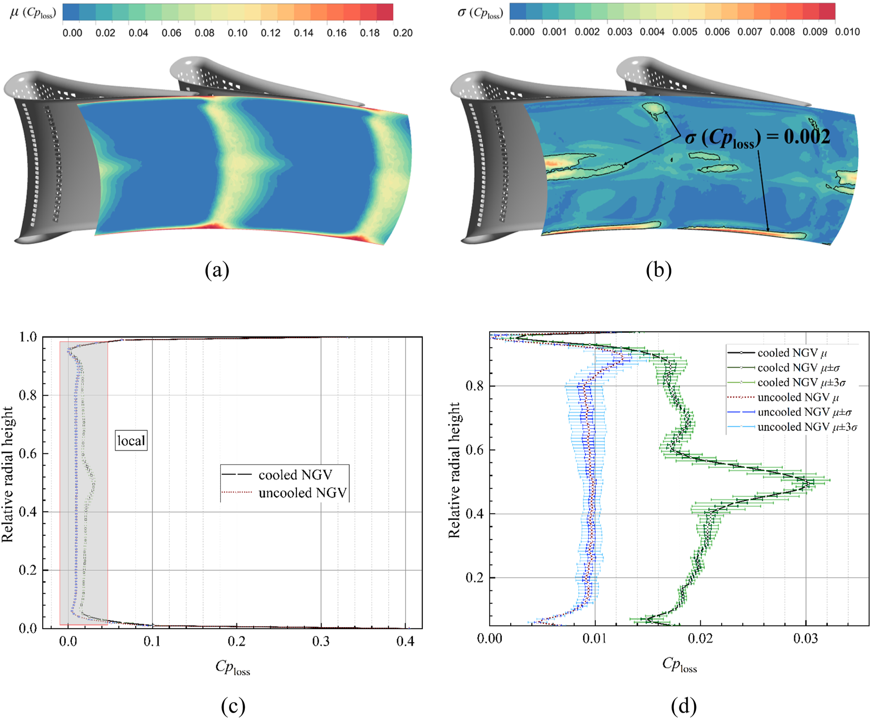
Uncertainty in the total pressure loss coefficient at the outlet of air-cooled guide vanes. (a) Average total pressure loss coefficient distribution. (b) Total pressure loss coefficient standard deviation distribution. (c) Total pressure loss coefficient distribution in radial direction. (d) Uncertainty in the total pressure loss coefficient in the local region.
The analysis reveals that cooled NGV exhibit an average total pressure loss coefficient fluctuation of 0.02424 with a standard deviation of 0.00098 at the exit plane under stochastic inlet conditions, attributable to coolant and mainstream mixing effects. These values represent an 80% and 42% increase compared to uncooled vane benchmarks (0.01345 average, 0.000688 standard deviation), translating to 0.098% of turbine inlet total pressure fluctuation magnitude. The relative variations of the mean Cploss are 0.52% and the standard deviation is 5.09%, which demonstrates that the influence of uncertainty in aerodynamic loss is over 5%. Aerodynamic loss concentrations persist in endwall regions and wake zones, since coolant mixing amplifies wake losses while diminishing secondary flow dominance. Counter-arranged leading edge film cooling holes generate counter-rotating vortex near midspan along both pressure side and suction side, particularly pronounced on the pressure side. This vortex interaction elevates midspan total pressure losses as visualized in Figure 10 through Q-criterion isosurface colored by turbulent kinetic energy, delineating the complex vortical structures within the meridional cascade channel.
FIGURE 10
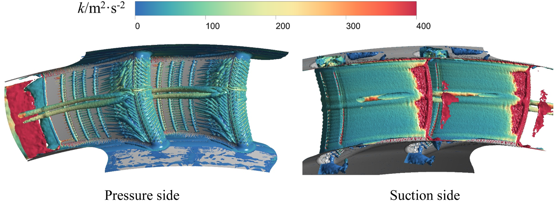
Structure of the vortex system in the air-cooled guide vane channel under the baseline hot streak condition (Q = 9.49 × 10⁵ s−2).
In contrast to the average total pressure loss characteristics, Figure 9b demonstrates persistent high fluctuation zones near the shroud associated with secondary flow interactions, alongside intensified loss fluctuations within counter-rotating vortex and wake mixing regions. These observations confirm that stochastic variations in hot streak and turbulence intensity not only modulate secondary flow intensity but also significantly influence coolant and mainstream mixing processes. Regions exceeding the 0.002 standard deviation threshold are delineated with black lines for focused comparative analysis, which equivalent to 10% of the mass-averaged total pressure loss coefficient at the exit plane. The radial uncertainty distribution in Figure 9d reveals elevated total pressure loss magnitudes and variability across cooled vanes, with maximum aerodynamic losses and fluctuation amplitudes concentrated at 40%–60% span. This midspan phenomenon stems from enhanced coolant entrainment by counter-rotating vortices, yielding peak loss coefficients of 0.03, which is 138% higher than uncooled vanes, and maximum fluctuations reaching 0.1% of turbine inlet total pressure, which gains 11% increase. Loss induced by secondary flow variability remains pronounced at shroud, though diminished in relative significance compared to coolant mixing regions.
Figures 11, 12 present the sensitivity index distributions of the total pressure loss coefficient at the cooled NGV exit to input variables and their correlation coefficient distributions, respectively. Among the three stochastic input parameters, the total pressure loss in high fluctuation zones exhibits the greatest sensitivity to turbine inlet turbulence intensity, accounting for 62% of the relative contribution. This is followed by hot streak radial position, accounting for 27% of the relative contribution, while the influence of hot streak circumferential position is minimal, accounting for 11%, consistent with the quantitative trends observed in uncooled vane configurations. The correlation coefficient contour maps reveal that within the 90% spanwise corner vortex regions near the exit, total pressure losses increase with elevated turbulence intensity and hot streak radial displacement. A divergent behavior emerges in the counter-rotating vortex regions downstream of adjacent vanes: the upper portion of the NGV1 vortex core demonstrates positive correlations with input parameters, whereas its lower section shows negative correlations. Conversely, NGV2 vortex system exhibits inverted polarity, with the total pressure loss fluctuations in these regions being markedly greater than those downstream of NGV1, as evidenced in Figure 9. This phenomenon is attributed to the distinct physical scales between primary and secondary hot streaks influencing coolant and mainstream interaction mechanisms.
FIGURE 11
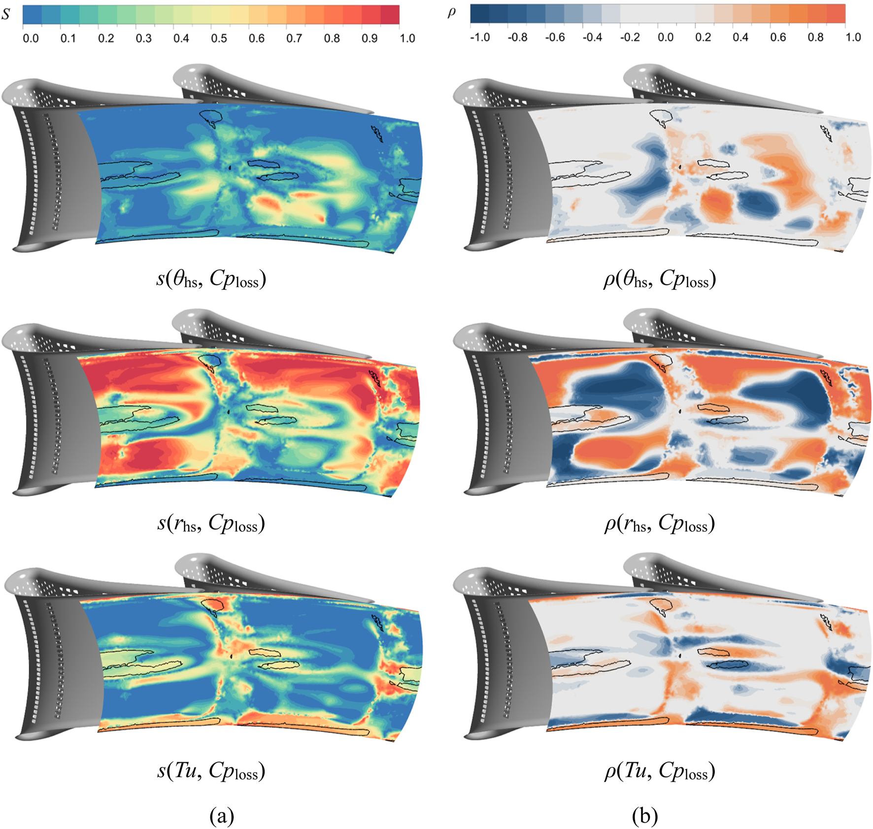
Distribution of sensitivity and correlation coefficients of total pressure loss coefficients at the outlet of air-cooled guide vanes to input variables. (a) Sensitivity index. (b) Correlation coefficient.
FIGURE 12
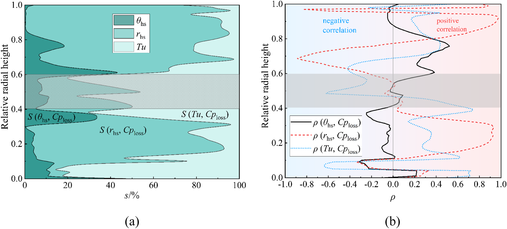
Radial distribution of the effect of each input parameter on the uncertainty of the total pressure loss coefficient. (a) Sensitivity percentage of each input parameter. (b) Correlation coefficient between each input parameter and output.
The influence of hot streak radial position variations is exemplified in Figure 13 through total temperature and total pressure contour maps at NGV exits under maximum and minimum radial displacement conditions, with green borders highlighting high fluctuation zones predominantly governed by wake interactions and midspan convergence of pressures side and suction side counter-rotating vortex. Figure 13a demonstrates that NGV2’s leading edge, which is subjected to the larger scale primary hot streak, exhibits broader high temperature fluid coverage compared to NGV1’s secondary hot streak exposure. Corresponding total pressure distributions reveal spatial alignment between high pressure and high temperature regions. Radial hot streak displacement from minimum to maximum positions intensifies temperature gradients, amplifying coolant and mainstream mixing that reduces total pressure in Local2 and Local3 regions. Conversely, total pressure increases in Local1 and Local4 zones due to thermal expansion effects outweighing mixing losses, manifesting as reduced loss coefficients. This mechanism explains the divergent correlation behaviors between total pressure loss and radial position near midspan regions downstream of adjacent vanes in Figure 11b. Turbulence intensity correlation discrepancies primarily arise from enhanced hot streak dissipation through cascade passages at elevated turbulence levels, producing thermal gradient effects analogous to radial position variations.
FIGURE 13
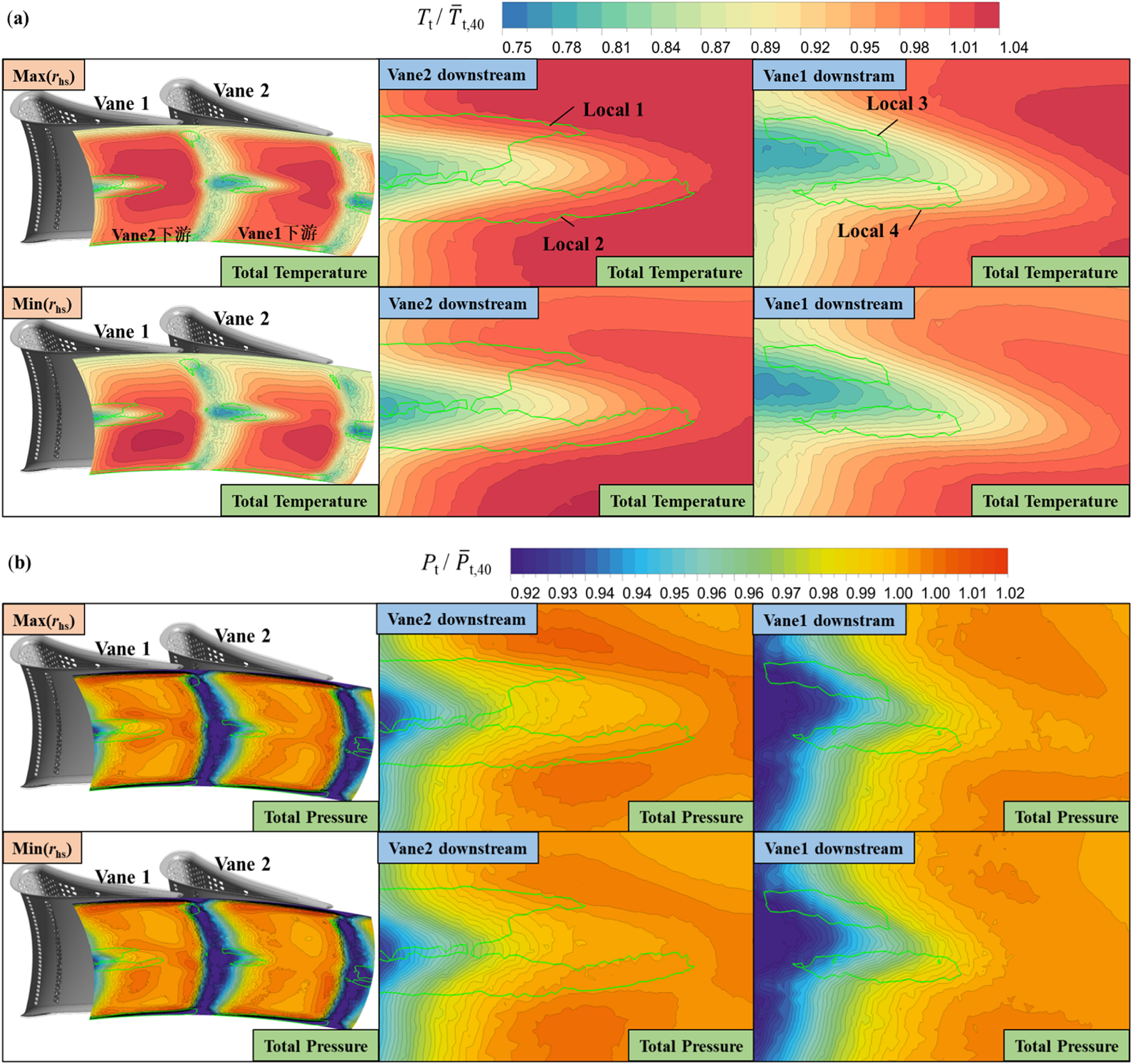
Distribution of total temperature and pressure at NGV outlet at the maximum and minimum radial positions of the hot streaks. (a) Total temperature at NGV outlet under different hot streaks radial positions. (b) Total pressure at NGV outlet under different hot streaks radial positions.
Uncertainty in Conjugate Heat Transfer Wall Temperature
Before analyzing the uncertainty in conjugate heat transfer wall temperature, the analysis of the influence of vortex structures on the metal surface temperature is conducted. Figure 14 presents the distributions of the vortex structures and the metal wall surface temperature. It can be observed that, due to the relatively dense arrangement of cooling holes on NGV, the temperature distribution on the NGV surface is relatively low and uniform. Whereas, the vortex structures near the wall are primarily vortex generated by coolant ejection. Particularly in the leading edge region, owing to the impinging arrangement of the film cooling holes, coolant impingement near 55% span produces significant vortex.
FIGURE 14
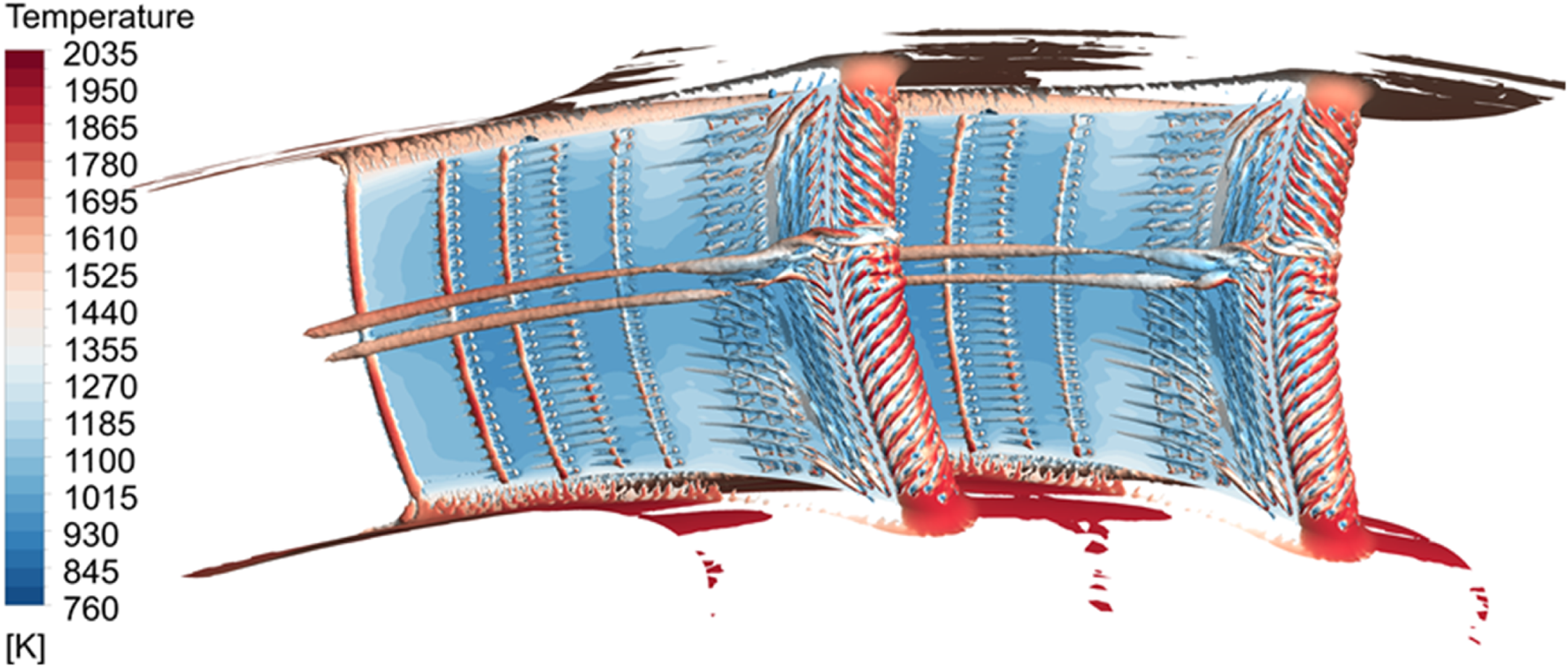
Vortex structures and NGV metal surface temperature distribution.
For cooled vanes, the coolant film partially shields NGV surface from hot mainstream gases through discrete hole effusion, theoretically mitigating thermal impacts from inlet condition variations. Whether such cooling protection sufficiently decouples metal temperatures from inflow uncertainties requires detailed investigation. Existing turbine UQ studies predominantly employ adiabatic film cooling effectiveness to assess cooling performance, yet this metric inadequately represents actual metal temperatures due to thermal conduction effects that homogenize local cooling variations. To address this limitation, the current work implements conjugate heat transfer analysis for metal temperature uncertainty quantification under stochastic inflow conditions. Figure 15 presents the computed uncertainty characterization of conjugate heat transfer surface temperatures for cooled NGV subjected to hot streak and turbulence intensity variations.
FIGURE 15
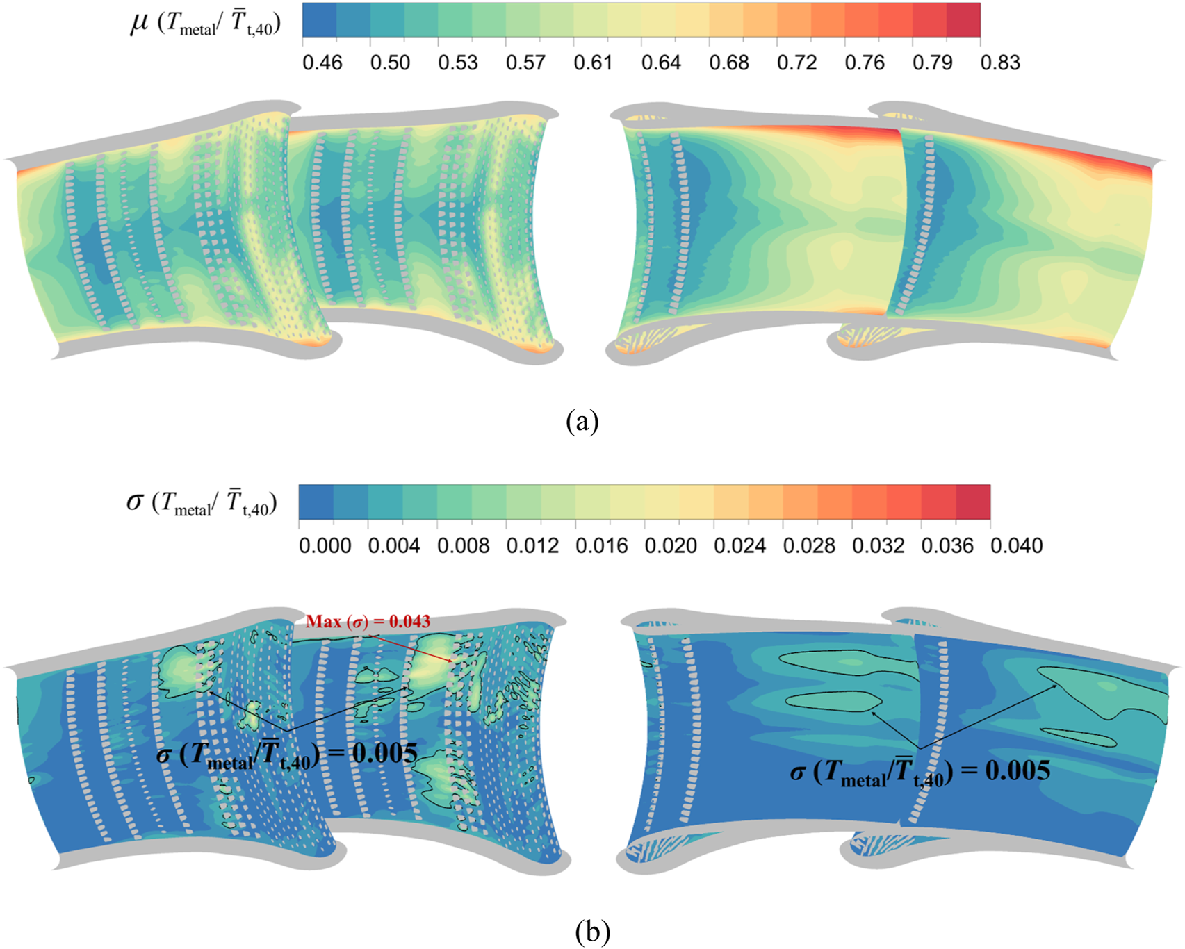
Uncertainty characterization of metal wall temperatures for cooled NGV conjugate heat transfer. (a) Average conjugate heat transfer wall temperature. (b) Standard deviation of conjugate heat transfer wall temperature.
The average metal temperature distribution reveals distinct cooling patterns shaped by leading edge counter-arranged film cooling holes, with twin cooling traces along midspan pressure side and suction side marking the trajectory of counter-rotating vortices. This demonstrates that while the counter-arranged hole configuration increases aerodynamic losses within NGV passages, it simultaneously enhances thermal protection, particularly in traditionally challenging regions like suction side trailing edges and pressure side midchord zones. To visualize the uncertainty in the wall temperature, Figure 16 quantifies this uncertainty through spanwise wall temperature profiles at 20%, 50%, and 80% span, showing peak dimensionless metal temperature reaching 0.83 with area averaged value of 0.565. On the suction side, secondary flows transport coolant from shroud regions toward midspan, generating an expanding high temperature band along the chordwise direction. The stagnation line exhibits elevated temperature due to ineffective coolant coverage under impinging mainstream flow. Pressure side cooling benefits from four rows of fan shaped holes downstream of 50% chord position, supplied by the aft cavity. However, in the middle chord length position, the positively curved NGV shape presents a convex profile on the pressure side, resulting in a larger jet angle of the cooling holes close to the shroud and hub, which causes the outflow of coolant to lift up without cooling the wall effectively, and thus the average value of temperature fluctuation is larger. The latter half of the suction side regio is mainly affected by the fully developed turbulence, which enhances the mixing with the main flow and hence the higher temperature.
FIGURE 16
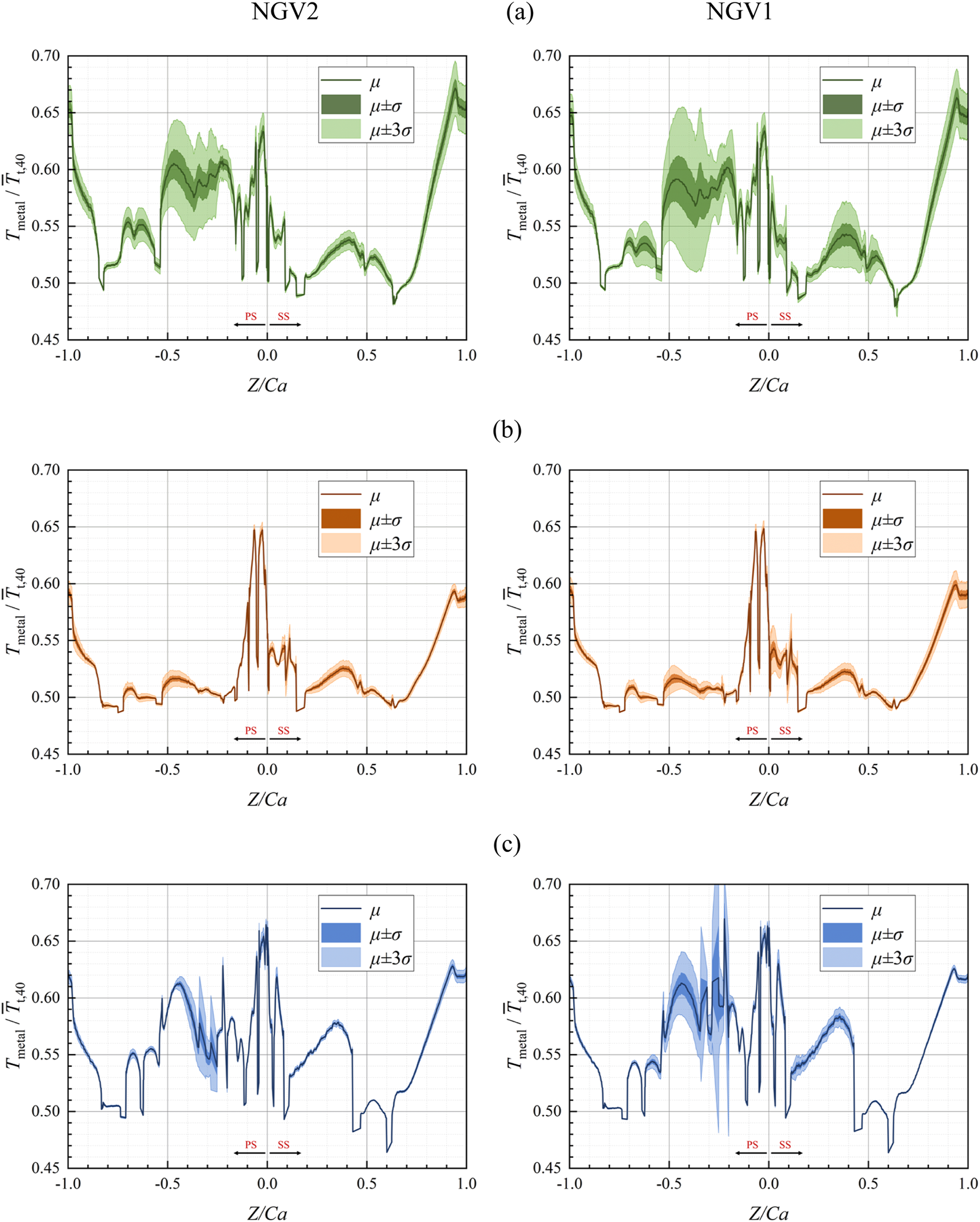
Average and fluctuating range of metal wall temperatures for different span in NGV. (a) 80% span. (b) 50% span. (c) 20% span.
The observed high temperature zones in the vane metal temperature distribution exhibit significant sensitivity to mainstream inlet condition variations, manifested through pronounced temperature fluctuations in standard deviation patterns. Combined with Figures 15, 16, it can be seen the overall dimensionless metal wall temperature of NGV does not fluctuate much, and the fluctuation amplitude of the area averaged wall temperature is 0.0027, but there are large fluctuations in the local position, and the local maximum fluctuation amplitude is 0.043. This indicates that the maximum fluctuation amplitude of the guide vane metal wall temperature occurs 84 K, which is up to 4.3% of the mainstream inlet average total temperature. To analyze the relative contribution of different fluctuating factors in the inlet conditions to the effect of uncertainty caused by the wall temperature, the distribution of the sensitivity of the metal wall temperature of the cooled NGV to the variation of the input parameters is given in Figure 17. Furthermore, to highlight the location of the regions with large temperature fluctuations for subsequent comparative analysis, Figure 17 details the sensitivity distribution of metal temperatures to input parameter variations, with regions exceeding 0.005 standard deviation (≥10 K) demarcated by black isolines, accounting for 14.1% of total vane surface area.
FIGURE 17
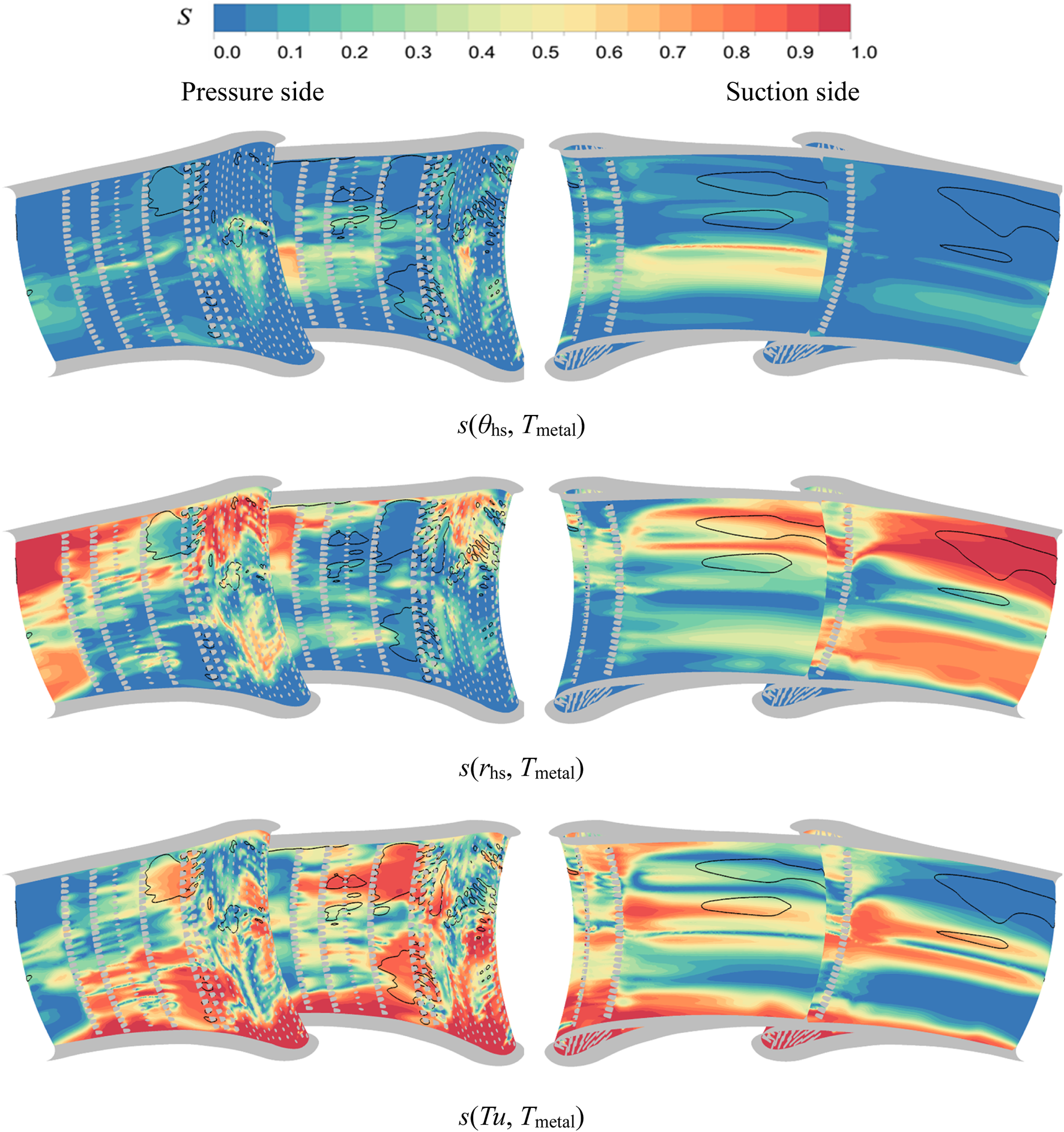
Sensitivity distribution of cooled NGV metal wall temperature to input parameter variations.
The analysis reveals that among the three stochastic input parameters investigated, variations in mainstream inlet turbulence intensity exert the dominant influence on metal temperature fluctuations, primarily affecting high fluctuation zones on the pressure side. Hot streak radial position variations exhibit secondary impacts, governing thermal uncertainty across both leading edge regions and suction side high fluctuation areas. In contrast, sensitivity to hot streak circumferential position changes remains minimal, with discernible effects confined to midspan leading edge zones. Figure 18 quantifies the relative contributions of input parameters to metal temperature uncertainty through regional sensitivity index distributions. For NGV2, circumferential position variations demonstrate less than 10% relative influence across all zones, while radial position and turbulence intensity exhibit comparable dominance over global temperature fluctuations. NGV1 displays distinct behavior: turbulence intensity maintains primary control over thermal variability, followed by radial position effects, with circumferential position remaining least influential. This differential sensitivity stems from vane specific flow interactions with primary and secondary hot streak structures under combustor-turbine coupling conditions.
FIGURE 18
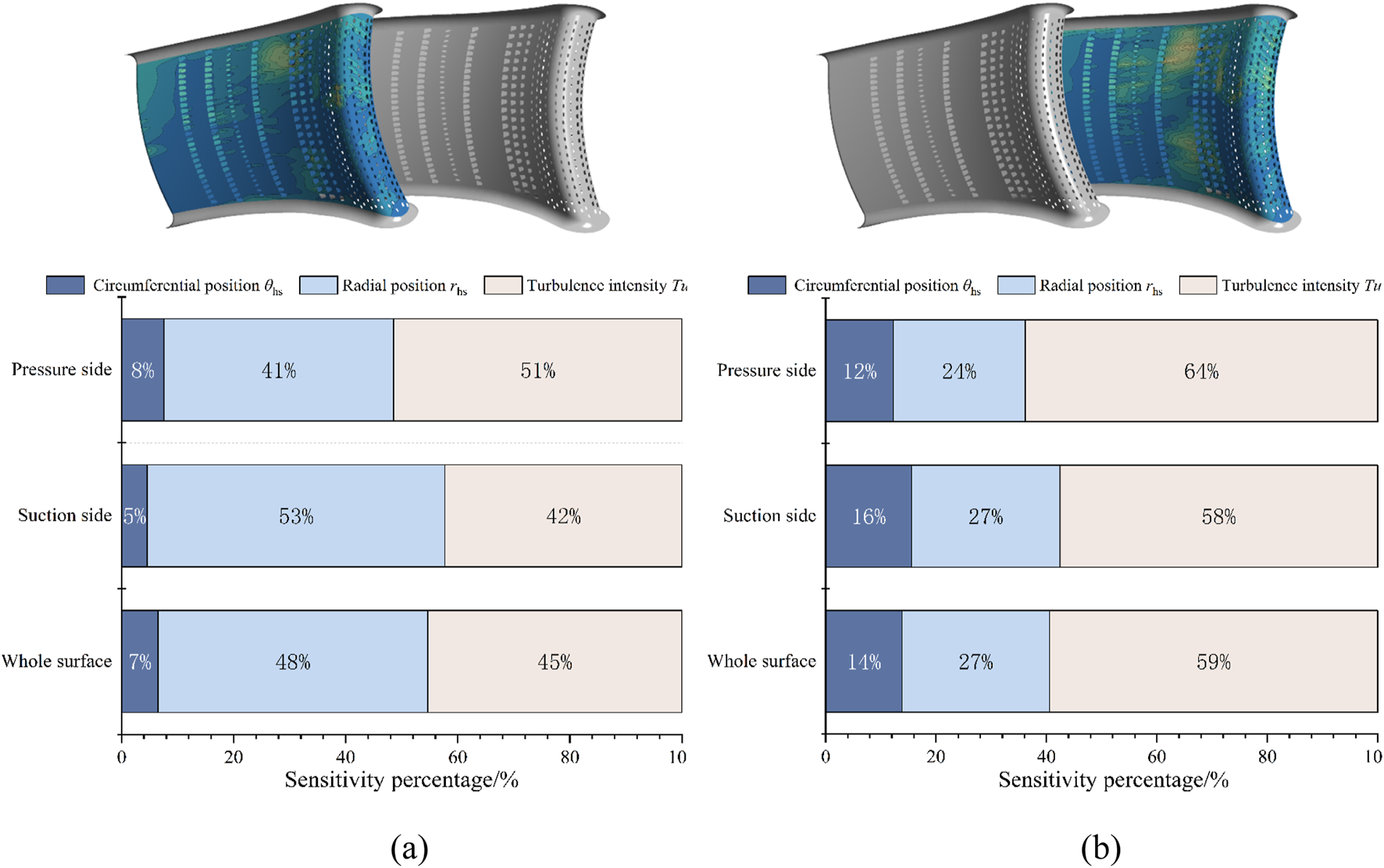
Percentage of relative effect of each input parameter on wall temperature in different regions of NGV. (a) NGV2. (b) NGV1.
The variation patterns of metal wall temperatures under varying turbine inlet conditions are analyzed through correlation coefficient distributions between input parameters and thermal responses, as illustrated in Figure 19. It can be found that the wall temperature of NGV1 increases with increasing circumferential position of the hot streak (from right to left), while the opposite is true for NGV2, with the region of higher correlation distributed near midspan regions. The pattern of influence of the radial position of the hot streak is relatively clear: positive correlations dominate 50%–90% spanwise height regions, contrasting with negative correlations at 20%–50% span. Notably, turbulence intensity effects diverge fundamentally between cooled and uncooled configurations. While uncooled vane adiabatic wall temperatures remain largely insensitive to turbulence variations, cooled vane conjugate heat transfer temperatures exhibit strong turbulence dependence. Elevated turbulence levels reduce temperatures in pressure side high fluctuation zones, while the effects on the leading edge and suction side temperatures diverge.
FIGURE 19
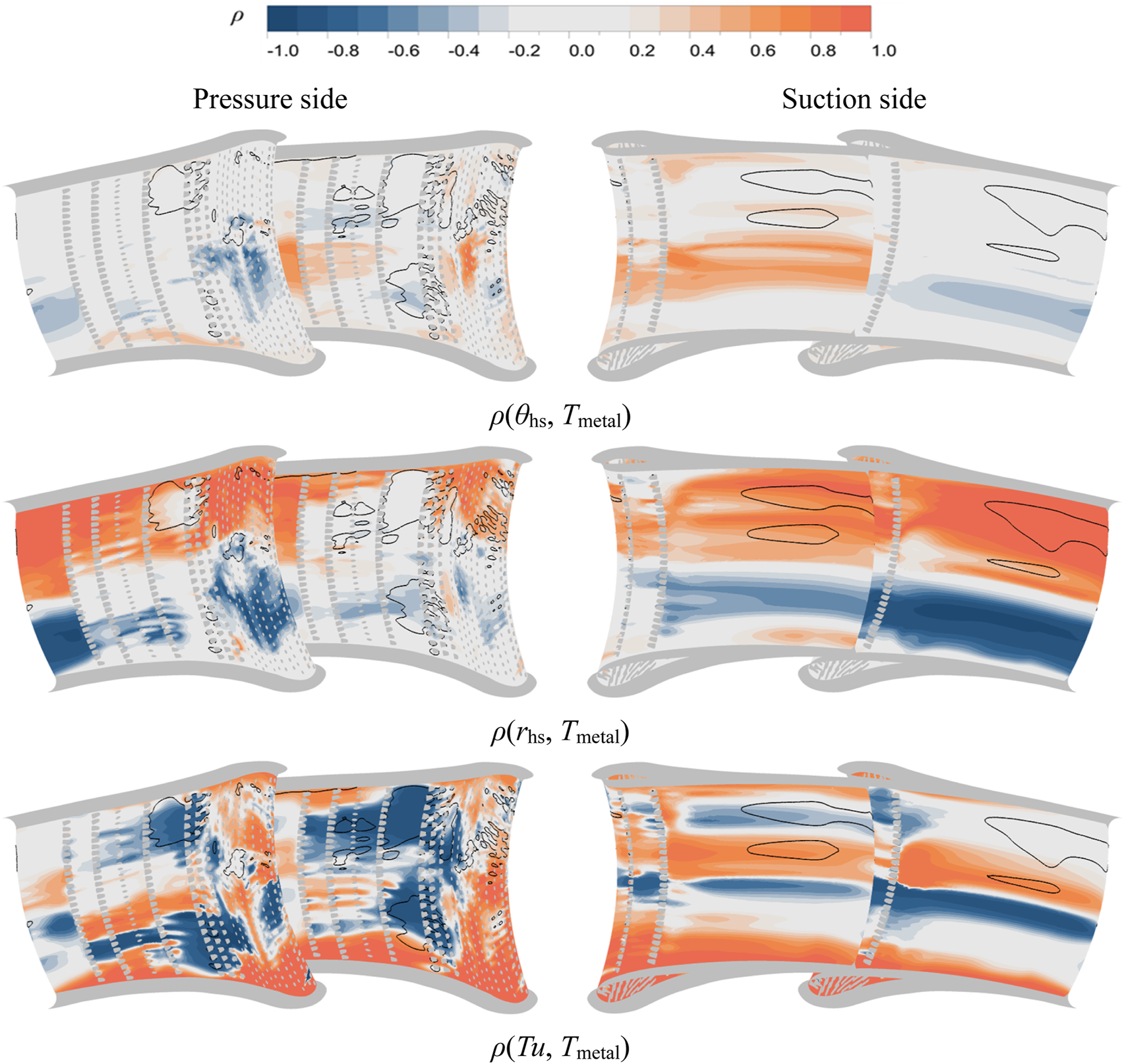
Distribution of correlation between input parameters and cooled NGV metal wall temperature variation.
The observed phenomena can be elucidated through the uncertainty quantification results, where uncooled vane adiabatic wall temperatures essentially represent the heat transfer driving temperature at the hot gas side in conjugate heat transfer system. Comparative analysis of correlation distributions in Figure 20 reveals that cooled NGV metal temperature responses to hot streak positional variations fundamentally mirror those of uncooled configurations. This indicates that for cooled vanes, uncertainties in hot streak circumferential and radial position primarily modify the wall heat transfer driving temperature, thereby inducing metal temperature fluctuations. However, coolant film coverage partially decouples metal temperatures from mainstream thermal variations. Regions with effective film protection exhibit diminished correlations between metal temperature and hot streak displacements, as the coolant layer attenuates direct thermal impacts from the hot gas path.
FIGURE 20
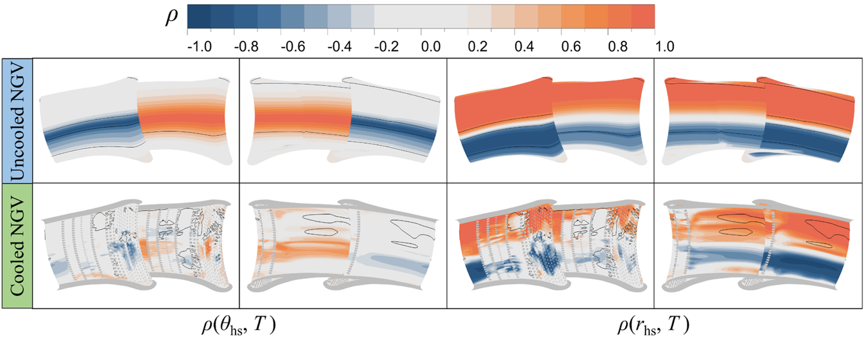
Comparison of location of hot streaks and distribution of temperature correlation of NGVs.
To analyze the different effects of turbulence intensity on cooled and uncooled vane thermal behavior, Figure 21 illustrates the cooling flow characteristics along the pressure side of NGV2 under varying turbulence levels. The shroud adjacent region receives combined cooling effects from pressure side fan-shaped holes and leading edge coolant injection, with the latter modifying pressure side cooling behavior. Elevated turbulence intensity from 10% to 20% enhances turbulent dispersion, improving coolant jet attachment through flattened jet core profiles and expanded lateral coverage. This improved coolant spreading reduces metal temperatures despite increased aerodynamic mixing losses, demonstrating turbulence intensity’s dual role in cooled vane thermos-aerodynamic performance.
FIGURE 21
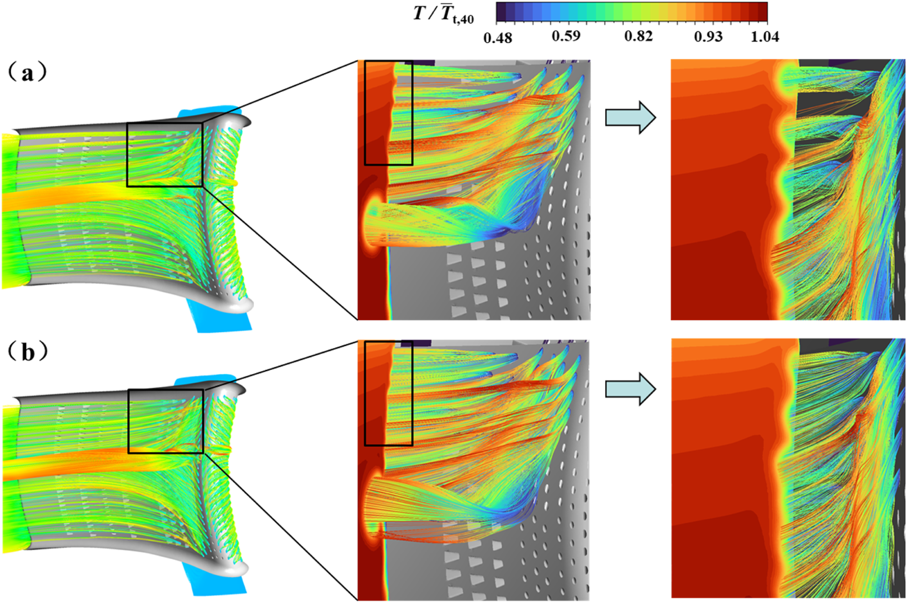
Characteristics of coolant flow at pressure side of NGV2 with different turbulence intensity. (a)Tu = 10%. (b)Tu = 20%.
The comprehensive analysis reveals that while the propagation of uncertainties in combustor-exit hot streak spatial position and mainstream turbulence intensity exerts limited influence on the global aerothermal performance of the investigated cooled NGV, localized effects prove substantial. The vane exit exhibits an average total pressure loss equivalent to 2.424% of inlet total pressure, with fluctuation amplitudes reaching 0.098% of the inlet reference value. The area averaged dimensionless metal temperature maintains 0.565 with 0.0027 variability, yet localized thermal fluctuations peak at 0.043, corresponding to 4.3% of the inlet total temperature. In addition, the region where the maximum fluctuation of wall temperature is higher than 30 K is considered as the high fluctuation region, then the area of this region accounts for 14.1% of the area of the entire NGV surface area (pressure side + suction side). Among the input parameters contributing to these uncertainties, turbulence intensity variations demonstrate dominant influence, followed by hot streak radial displacement, with circumferential positioning exhibiting minimal impact. This hierarchy aligns with flow physics governing coolant and mainstream interactions: enhanced turbulent mixing modifies film cooling coverage effectiveness, while radial hot streak shifts alter thermal gradients across critical cooling zones. Circumferential variations primarily affect stagnation line heat transfer characteristics, mitigated through leading edge cooling configurations.
Conclusion
This study establishes a comprehensive framework for quantifying aerothermal uncertainties in high-pressure turbine nozzle guide vanes (NGV) under combustor-turbine interaction, integrating parametric modeling, non-intrusive polynomial chaos expansion (PCE), and Sobol sensitivity analysis. The key findings are summarized as follows:
1) The propagation of combustor-exit hot streak and turbulence intensity uncertainties significantly amplifies total pressure loss variability in cooled NGVs. Cooled configurations exhibit an 80% increase in average total pressure loss and 42% higher fluctuation amplitude, predominantly driven by enhanced coolant and mainstream mixing and counter-rotating vortex interactions. Midspan regions (40%–60% span) experience peak losses of 0.03, which gains a 138% increase compared with uncooled NGV, attributable to turbulent entrainment effects. Secondary flow dominated zones near endwall show reduced relative significance compared to mixing driven loss mechanisms.
2) Conjugate heat transfer analysis reveals localized metal temperature fluctuations, up to 0.043 dimensionless temperature (4.3% of inlet total temperature), despite moderate surface-averaged variability of 0.0027. High fluctuation regions of 14.1% of NGV surface area is associated with cooling effectiveness transitions and secondary flow migration paths. Turbulence intensity dominates temperature uncertainty, particularly on pressure surfaces, while hot streak radial positioning governs suction surface thermal variability. Circumferential hot streak shifts exhibit minimal influence, mitigated by leading edge cooling configurations.
3) Vane specific flow interactions yield contrasting sensitivity hierarchies: NGV1 exhibits turbulence dominated thermal responses, whereas NGV2 demonstrates balanced contributions from turbulence and radial hot streak displacement. This divergence stems from primary and secondary hot streak scaling effects and coolant redistribution. Elevated turbulence intensity improves pressure side film coverage through enhanced jet dispersion but exacerbates suction side thermal gradients due to accelerated film dissipation.
4) The developed PCE based UQ system demonstrates efficacy in decoupling global and localized aerothermal uncertainties under realistic combustor-turbine coupling conditions. By resolving the interplay between hot streak spatial dynamics, turbulence driven mixing, and cooling system performance, this framework provides actionable insights for optimizing cooling architectures under probabilistic design paradigms. The integration of Hammersley sampling and collocation methods ensures computational efficiency, enabling high-fidelity uncertainty propagation analyses for industrial applications.
Statements
Data availability statement
The raw data supporting the conclusions of this article will be made available by the authors, without undue reservation.
Author contributions
RL: Writing – review and editing, Writing – original draft, Formal analysis, Conceptualization. LW: Formal analysis, Methodology. ZW: Investigation, Funding acquisition. BZ: Methodology. XD: Investigation. JL: Investigation. XW: Investigation. ZF: Funding acquisition, Supervision, Project administration. All authors contributed to the article and approved the submitted version.
Funding
The author(s) declare that financial support was received for the research and/or publication of this article. This work was supported by the National Science and Technology Major Project (J2019-II-0008-0028), and National Natural Science Foundation of China (Project No. 52106122).
Conflict of interest
Author BZ was employed by the company Shanghai Electric Power Generation Equipment Co., Ltd.
The remaining authors declare that the research was conducted in the absence of any commercial or financial relationships that could be construed as a potential conflict of interest.
Generative AI statement
The author(s) declare that Generative AI was used in the creation of this manuscript. ChatGPT 3.5 was used to check the correctness of English writing.
References
1.
Bacci T Becchi R Picchi A Facchini B . Adiabatic Effectiveness on High-Pressure Turbine Nozzle Guide Vanes under Realistic Swirling Conditions. ASME J Turbomach (2019) 141(1):011009. 10.1115/1.4041559
2.
Bunker RS . Evolution of Turbine Cooling. In: Proceedings of the ASME Turbo Expo: Turbine Technical Conference and Exposition, 1 (2017). 10.1115/gt2017-63205
3.
Li J Li ZY Li ZG Zhang KY Song LM . Aerothermal Performance of High Pressure Turbine Stage with Combustor-Turbine Interactions: Review. ACTA Aeronauticaet Astronautica Sinica (2021) 42(3):24111–024111.
4.
Bunker RS . Gas Turbine Heat Transfer: Ten Remaining Hot Gas Path Challenges. ASME J Turbomach (2007) 129(2):193–201. 10.1115/1.2464142
5.
Feng ZP Wang ZD Liu ZF . Review on Research of Hot Streak Migration Mechanisms in Gas Turbine Stage. Proc CSEE (2014) 34(29):5120–30.
6.
Salvadori S Montomoli F Martelli F Adami P Chana KS Castillon L . Aerothermal Study of the Unsteady Flow Field in a Transonic Gas Turbine with Inlet Temperature Distortions. ASME J Turbomach (2011) 133(3):031030. 10.1115/1.4002421
7.
Feng ZP Liu ZF Shi Y Wang ZD . Effects of Hot Streak and Airfoil Clocking on Heat Transfer and Aerodynamic Characteristics in Gas Turbine. ASME J Turbomach (2016) 138(2):021002. 10.1115/1.4031785
8.
Ames FE Moffat RJ . Effects of Simulated Combustor Turbulence on Boundary Layer Heat Transfer (1990). p. 11–7.
9.
Krishnamoorthy V Sukhatme SP . The Effect of Free-Stream Turbulence on Gas Turbine Blade Heat Transfer. J Turbomach (1989) 111(4):497–501. 10.1115/1.3262299
10.
Mehendale AB Han JC Ou S . Influence of High Mainstream Turbulence on Leading-Edge Heat-Transfer. ASME J Heat Transfer (1991) 113(4):843–50. 10.1115/1.2911212
11.
Wang ZD Liu ZF Feng ZP . Influence of Mainstream Turbulence Intensity on Heat Transfer Characteristics of a High Pressure Turbine Stage with Inlet Hot Streak. ASME J Turbomach (2016) 138(4):041005. 10.1115/1.4032062
12.
Montomoli F Carnevale M Massini M Ammaro A Salvadori S . Uncertainty Quantification in Computational Fluid Dynamics and Aircraft Engines. Springer International Publishing AG (2015).
13.
Song YJ Nie J Guo ZD Song LM . Uncertainty Quantification of Heat Transfer Performance of High Temperature Blade. J Eng Thermophys (2015)(8) 6.
14.
Xiao D Li CX Song LM Li J . Influence of Uncertainty Arising from Squealer Depth and Blowing Ratio on Cooling Characteristics of Rotor Tips. J Eng Thermophys (2020) 41(7):8.
15.
Huang M Li J Li ZG Song LM . Investigations on Uncertainty Quantification of Film Cooling Effectiveness and Aerodynamic Performance of Turbine Blade Squealer Tip. J Xi'an Jiaotong Univ (2021) 55(05):181–92.
16.
Montomoli F D'Ammaro A Uchida S . Uncertainty Quantification and Conjugate Heat Transfer: A Stochastic Analysis. ASME J Turbomach (2013) 135(3):99–108. 10.1115/gt2012-68203
17.
Schneider M . Robust Aero-Thermal Design of High Pressure Turbines at Uncertain Exit Conditions of Low-Emission Combustion Systems. Darmstadt (2019).
18.
Schneider M Schiffer HP Lehmann K , Uncertainty Propagation Analyses of Lean Burn Combustor Exit Conditions for a Robust Nozzle Cooling Design. ASME J Turbomach (2020). 142, 051003, 10.1115/1.40464215).
19.
Zhang WH Wang ZD Wang ZH Li RC Feng ZP . Study on Heat Transfer Characteristics of NGVs Influenced by Non-Reacting Lean Burn Combustor Simulator Flow. Int J Therm Sci (2022) 172.
20.
Hylton LD Nirmalan V Sultanian BK Kaufman RM . The Effects of Leading Edge and Downstream Film Cooling on Turbine Vane Heat Transfer. Final report general motors corp. Indianapolis in. Allison gas turbine div (1988).
21.
Wang ZD Wang D Wang ZH Feng ZP . Heat Transfer Analyses of Film-Cooled HP Turbine Vane Considering Effects of Swirl and Hot Streak. Appl Therm Eng (2018) 142:815–29. 10.1016/j.applthermaleng.2018.07.044
22.
Wang ZH Wang ZD Zhang WH Feng ZP . Numerical Study on Unsteady Film Cooling Performance of Turbine Rotor Considering Influences of Inlet Non-Uniformities and Upstream Coolant. Aerospace Sci Technology (2021) 119.
23.
Charbonnier D Ott P Jonsson M Kobke T Cottier F . Comparison of Numerical Investigations with Measured Heat Transfer Performance of a Film Cooled Turbine Vane. Proc Asme Turbo Expo (2008) 4:571–82.
24.
Jiang YT Zheng Q Dong P Zhang H Yu FL . Research on Heavy-Duty Gas Turbine Vane High Efficiency Cooling Performance Considering Coolant Phase Transfer. Appl Therm Eng (2014) 73(1):1177–93. 10.1016/j.applthermaleng.2014.09.023
25.
Wiener N . The Homogeneous Chaos. Am J Mathematics (1938) 60:897–936. 10.2307/2371268
26.
Xiu DB Karniadakis GE . The Wiener-Askey Polynomial Chaos for Stochastic Differential Equations. SIAM J Scientific Comput (2002) 24(2):619–44. 10.1137/s1064827501387826
27.
Anile AM Spinella S Rinaudo S . Stochastic Response Surface Method and Tolerance Analysis in Microelectronics. The Int J Comput Mathematics Electr Electron Eng (2003) 22(2):314–27.
28.
West TK Hosder S . Uncertainty Quantification of Hypersonic Reentry Flows with Sparse Sampling and Stochastic Expansions. J Spacecraft Rockets (2015) 52(1):120–33. 10.2514/1.a32947
29.
Najm HN . Uncertainty Quantification and Polynomial Chaos Techniques in Computational Fluid Dynamics. Annu Rev Fluid Mech (2009) 41:35–52. 10.1146/annurev.fluid.010908.165248
30.
Hosder S Walters R Balch M . Efficient Sampling for Non-Intrusive Polynomial Chaos Applications with Multiple Uncertain Input Variables. In: 48th AIAA/ASME/ASCE/AHS/ASC Structures, Structural Dynamics, and Materials Conference.
31.
Sudret B . Global Sensitivity Analysis Using Polynomial Chaos Expansions. Reliability Eng and Syst Saf (2008) 93(7):964–79. 10.1016/j.ress.2007.04.002
32.
Crestaux T Le Maıˆtre O Martinez J-M . Polynomial Chaos Expansion for Sensitivity Analysis. Reliability Eng and Syst Saf (2009) 94(7):1161–72. 10.1016/j.ress.2008.10.008
33.
Schaefer J Hosder S West T Rumsey C Carlson JR Kleb W . Uncertainty Quantification of Turbulence Model Closure Coefficients for Transonic Wall-Bounded Flows. AIAA J (2017) 55(1):195–213. 10.2514/1.j054902
Summary
Keywords
nonuniform inlet flow, aerothermal characteristics, uncertainty quantization, polynomial chaos expansion, combustor-turbine interaction
Citation
Li R, Wang L, Wang Z, Zhang B, Du X, Li J, Wang X and Feng Z (2025) Uncertainty Quantification for Aerothermal Characteristics of HP Turbine Vanes Under Combined Hot-Streak and Turbulence Intensity Effects. Aerosp. Res. Commun. 3:14801. doi: 10.3389/arc.2025.14801
Received
22 April 2025
Accepted
13 August 2025
Published
29 August 2025
Volume
3 - 2025
Updates
Copyright
© 2025 Li, Wang, Wang, Zhang, Du, Li, Wang and Feng.
This is an open-access article distributed under the terms of the Creative Commons Attribution License (CC BY). The use, distribution or reproduction in other forums is permitted, provided the original author(s) and the copyright owner(s) are credited and that the original publication in this journal is cited, in accordance with accepted academic practice. No use, distribution or reproduction is permitted which does not comply with these terms.
*Correspondence: Zhenping Feng, zpfeng@mail.xjtu.edu.cn
Disclaimer
All claims expressed in this article are solely those of the authors and do not necessarily represent those of their affiliated organizations, or those of the publisher, the editors and the reviewers. Any product that may be evaluated in this article or claim that may be made by its manufacturer is not guaranteed or endorsed by the publisher.